


Index - 1 Index - 1
INDEX
[A]
Absolute maximum input................................. 3-2
Accuracy...................................................3-1, 3-9
A/D conversion completed flag............3-12, 3-15
A/D conversion enable/disable setting 3-10, 3-20
A/D conversion methods............................... 3-10
A/D converter module .....................................A-9
Analog input..................................................... 3-1
Applicable modules ......................................... 2-1
Automatic refresh settings .....................5-1, 5-13
Averaging processing setting........................ 3-21
Averaging processing.................................... 3-10
[B]
Buffer memory............................................... 3-17
[C]
Channel change completed flag................... 3-15
Channel change request............................... 3-16
CH
Average time/
average number of times .............................. 3-20
Close file........................................................ 5-11
Conversion speed ........................................... 3-2
Current input characteristics ........................... 3-6
[D]
Dedicated instruction..................................App.-3
Delete file....................................................... 5-11
Digital output values...................................... 3-22
Digital output.................................................... 3-1
[E]
EMC directive ..................................................A-9
Error clear request......................................... 3-16
Error code list .................................................. 8-1
ERROR LED ................................................... 4-3
Error flag........................................................ 3-15
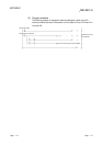
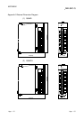
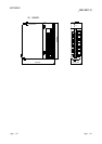
External dimension diagram ....................App.-15
External wiring................................................. 4-6
[F]
Function version ..........................1-2, 2-3, App.-1
[G]
Gain value ........................................................3-2
GX Configurator-AD.........................................2-2
GX Configurator-AD software version.2-3, App-2
GX Developer ..........................................A-9, 2-2
[H]
Handling precautions.......................................4-1
High resolution mode.......................................3-1
High resolution mode status flag...................3-13
[ I ]
I/O assignment setting.....................................4-9
I/O characteristics ............................................3-1
Industrial shipment settings offset/gain value
........................................................................3-26
Input range ............................................. 3-23, 4-8
Install ................................................................5-2
Intelligent function module parameter.............5-6
Intelligent function module utility
parameter setting module select screen.........5-8
Internal current consumption...........................3-2
[L]
List of I/O signals ...........................................3-12
[M]
Maximum and minimum values
hold function...................................................3-12
Maximum and minimum values
storage area...................................................3-24
Maximum resolution.........................................3-1
Maximum value/minimum value reset
completed flag................................................3-15
Maximum value/minimum value
reset request ..................................................3-16
Mode switching setting ..................................3-25
Module READY..............................................3-13
Monitor/test.....................................................5-15
Multiple PLC system........................................2-1
[N]
Normal resolution mode ..................................3-1
Number of occupied points..............................3-2
Ind