


3 - 17 3 - 17
MELSEC-Q
3 SPECIFICATIONS
3.4 Buffer Memory
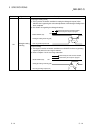
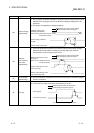
The detailed explanation of the buffer memory in Section 3.4.4 and later is based on
the 8-channel analog input (CH. 1 to CH. 8) Q68ADV/Q68ADI.
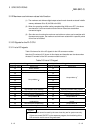
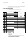
3.4.1 Buffer memory assignment (Q64AD)
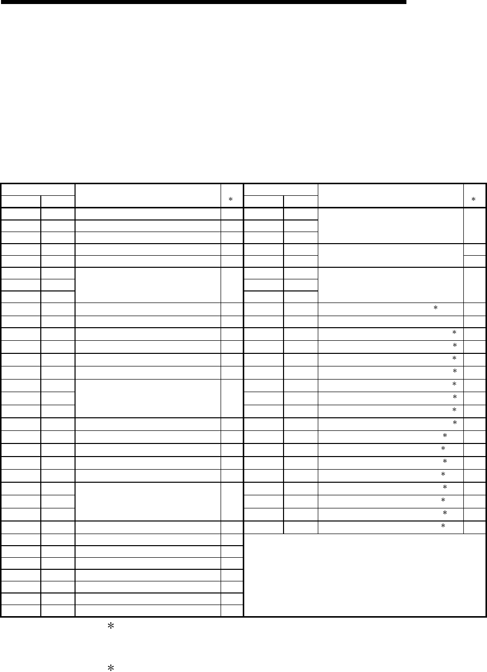
This section describes the assignment of the Q64AD buffer memory.
Table 3.4 Buffer memory assignment (Q64AD)
Address Address
Hexadecimal Decimal
Description
R/W
1
Hexadecimal Decimal
Description
R/W
1
0 H 0 A/D conversion enable/disable setting R/W 26 H 38
1
H
1 CH1 Average time/average number of times R/W to to System area —
2
H
2 CH2 Average time/average number of times R/W 9D
H
157
3 H 3 CH3 Average time/average number of times R/W 9E H 158 R/W
4 H 4 CH4 Average time/average number of times R/W 9F H 159
Mode switching setting
R/W
5 H 5A0 H 160
to to System area — to to System area —
8 H 8C7 H 199
9
H
9 Averaging process setting R/W C8
H
200
Pass data classification setting
2
R/W
A H 10 A/D conversion completed flag R C9 H 201 System area —
B H 11 CH1 Digital output value R CA H 202
CH1 Industrial shipment settings offset value
2
R/W
C
H
12 CH2 Digital output value R CB
H
203
CH1 Industrial shipment settings gain value
2
R/W
D
H
13 CH3 Digital output value R CC
H
204
CH2 Industrial shipment settings offset value
2
R/W
E
H
14 CH4 Digital output value R CD
H
205
CH2 Industrial shipment settings gain value
2
R/W
F
H
15 CE
H
206
CH3 Industrial shipment settings offset value
2
R/W
to to System area — CF
H
207
CH3 Industrial shipment settings gain value
2
R/W
12
H
18 D0
H
208
CH4 Industrial shipment settings offset value
2
R/W
13
H
19 Error code R D1
H
209
CH4 Industrial shipment settings gain value
2
R/W
14 H 20 Setting range (CH1 to CH4) R D2 H 210
CH1 User range settings offset value
2
R/W
15 H 21 System area — D3 H 211
CH1 User range settings gain value
2
R/W
16
H
22 Offset/gain setting mode Offset specification R/W D4
H
212
CH2 User range settings offset value
2
R/W
17 H 23 Offset/gain setting mode Gain specification R/W D5 H 213
CH2 User range settings gain value
2
R/W
18
H
24 D6
H
214
CH3 User range settings offset value
2
R/W
to to System area — D7 H 215
CH3 User range settings gain value
2
R/W
1D
H
29 D8
H
216
CH4 User range settings offset value
2
R/W
1E H 30 CH1 Maximum value R/W D9 H 217
CH4 User range settings gain value
2
R/W
1F H 31 CH1 Minimum value R/W
20
H
32 CH2 Maximum value R/W
21
H
33 CH2 Minimum value R/W
22
H
34 CH3 Maximum value R/W
23
H
35 CH3 Minimum value R/W
24
H
36 CH4 Maximum value R/W
25
H
37 CH4 Minimum value R/W
1 Indicates whether reading and writing to/from a sequence program are enabled.
R : Read enabled
W : Write enabled
2 Areas used to restore the user range settings offset/gain values when online
module change is made.
Refer to chapter 7 for details of online module change.