


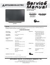


MODEL: WD-52531 / WD-62531 / WD-62530
Page 5
INTRODUCTION
This service manual provides service instructions for LCD Projection TV Models WD-52531 and WD-62531 using the
V32 chassis, and WD-62530 using the V32L chassis.
This service manual includes:
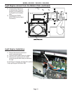
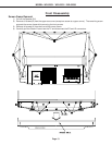
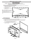
1. Assembly and disassembly instructions for the front and rear cabinet components.
2. Servicing of the Lenticular Screen and Fresnel Lens.
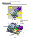
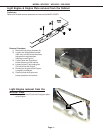
3. Servicing down to major components, chassis, PWBs, Light Engine, Lamp Ballast, etc..
4. Electrical adjustments.
5. Optical Adjustments.
6. Lead Free Soldering.
7. Chip parts replacement procedures.
8. Simplified circuit path diagrams.
The parts list section of this service manual includes:
1. Cabinet and screen parts.
2. Electrical parts.
Block diagrams of the above listed models are included in this service manual for better understanding of the circuitry.
PRODUCT SAFETY NOTICE
Many electrical and mechanical parts in television receivers have special safety related characteristics. These charac-
teristics are often not evident from visual inspection nor can the protection afforded by them necessarily be obtained by
using replacement components rated for higher voltage, wattage, etc.
Replacement parts which have special safety characteristics are identified in this service manual.
Electrical components having such features are identified by shading on the schematic diagram and by bold type in
the parts list of this service manual. Therefore, the replacement for any safety part should be identical in value
and characteristics.
Pb Solder
The PWBs used in the V32 chassis are constructed using Lead-Free solder. When servicing use
only recommended Lead-Free solder (refer to page 26).