


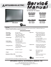


MODELS: WD-52627 / 52628 / 62627 / 62628 / 62827 / 62927 / 73727 / 73827 / 73927
Page 4
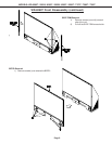
SERVICE PARTS LIST .................................................................................................................... 56
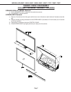
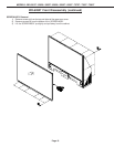
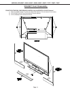
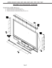
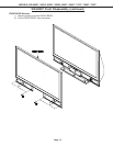
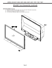
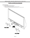
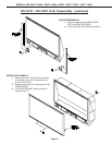
SCREEN ASSEMBLY PARTS LIST.................................................................................................. 67
WD-52627 / WD-52628 / WD-62627 / WD-62628 .......................................................................... 67
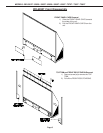
WD-62827 / WD-62927 ................................................................................................................. 68
WD-73727 / WD-73827 / WD-73927 ............................................................................................. 69
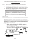
CIRCUITRY BLOCK DIAGRAMS ..................................................................................................... 71
Main Power Supply ....................................................................................................................... 71
Lamp Ballast DC Supply ............................................................................................................... 72
Fans Power Supply....................................................................................................................... 72
Optical Engine Power Supply........................................................................................................ 73
HDD Power Supply ((V30+ & V31 Only)........................................................................................ 73
Analog Video Signal Path ............................................................................................................. 74
Digital Video Signal Path .............................................................................................................. 75
HDD Record Signal Path............................................................................................................... 76
Sound Signal Path ........................................................................................................................ 77
Command Input Circuitry............................................................................................................... 78
Serial Data Control Lines .............................................................................................................. 78
Lamp Control Circuitry .................................................................................................................. 79
Lamp, Engine and Fan’s Protect circuitry ..................................................................................... 80
TV Guide On screen®................................................................................................................... 80
SCHEMATIC DIAGRAMS .....................................................................................................................
PCB LAYOUT DIAGRAMS ...................................................................................................................