


PAGE 53
MODELS: WD-52627 / 52628 / 62627 / 62628 / 62827 / 62927 / 73727 / 73827 / 73927
CHIP PARTS REPLACEMENT
Some resistors, shorting jumpers (0 Ohm resistors),
ceramic capacitors, transistors and diodes are chip parts.
The following precautions should be taken when replacing
these parts.
Cautions:
1. Use a fine tipped, well insulated soldering iron
and tweezers.
2. Melt the solder and remove the chip parts
carefully so as not to tear the copper foil from
the printed circuit board.
3. Discard removed chips; do not reuse them.
4. Do not apply heat for more than 3 (three)
seconds to new chip parts.
5. Avoid using a rubbing stroke when soldering.
6. Take care not to scratch, or damage the chip
parts when soldering.
7. Supplementary cementing is not required.
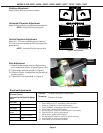
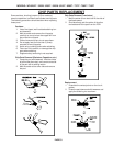
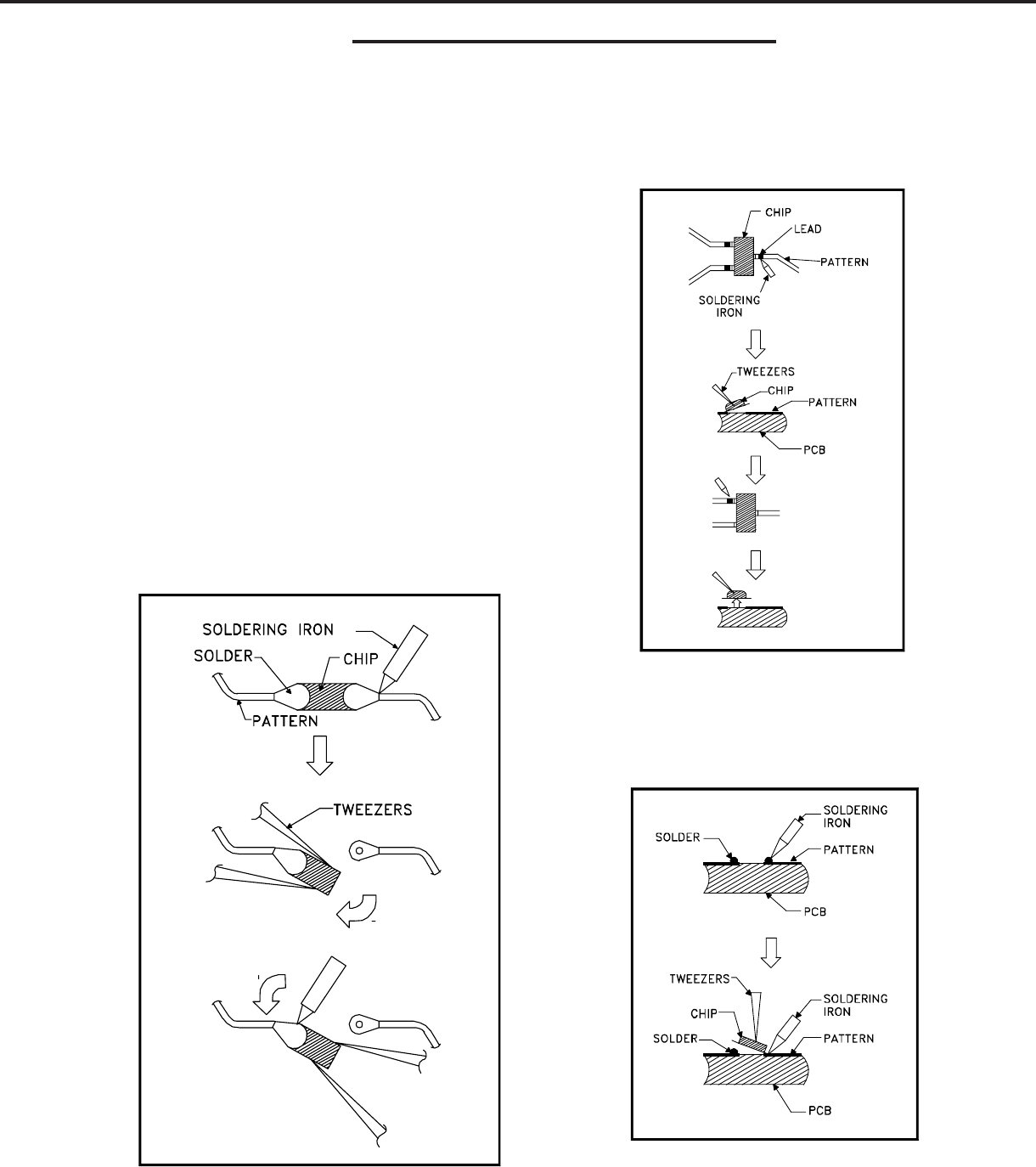
Chip Parts Removal (Resistors, Capacitors, etc.)
1. Grasp the part with tweezers. Melt the solder
at both sides alternately, and remove one side
of the part with a twisting motion.
2. Melt the solder at the other side and remove
the part.
Chip Parts Removal (Transistors)
1. Melt the solder of one lead and lift the side of
that lead upward.
2. Simultaneously melt the solder of the other
two leads and lift the part from the PCB.
Replacement
1. Presolder the contact points on the circuit
pattern.
2. Press the part downward with tweezers and
apply the soldering iron as shown.