


MODELS: WD-52627 / 52628 / 62627 / 62628 / 62827 / 62927 / 73727 / 73827 / 73927
Page 49
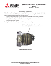
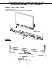
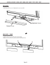
WD-73927
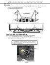
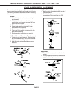
1) Remove (16) screws (A). 8 on each side. (Remove only the outside screws. Do not remove inside
screws, they are for the Screen Frame)
2) Pull Front Panel Escushions from unit.
3) Remove (8) screws (B) and remove the Pedestal Cover. Mechanical adjuster is now accessable.
BB
A
A
A
A
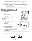
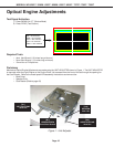
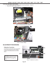
Locking Screws and Wedge Removal
Before mechanical adjustments can be made, locking screws must be loosened.
• [B-1] is located on the front of the UNIT-ADJUSTER. (Figure 1)
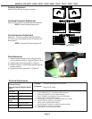
• In 52” and 62” models [B-2] is accessible from the rear of the unit on the right side of the
Optical Engine (from the rear). (Figure 2)
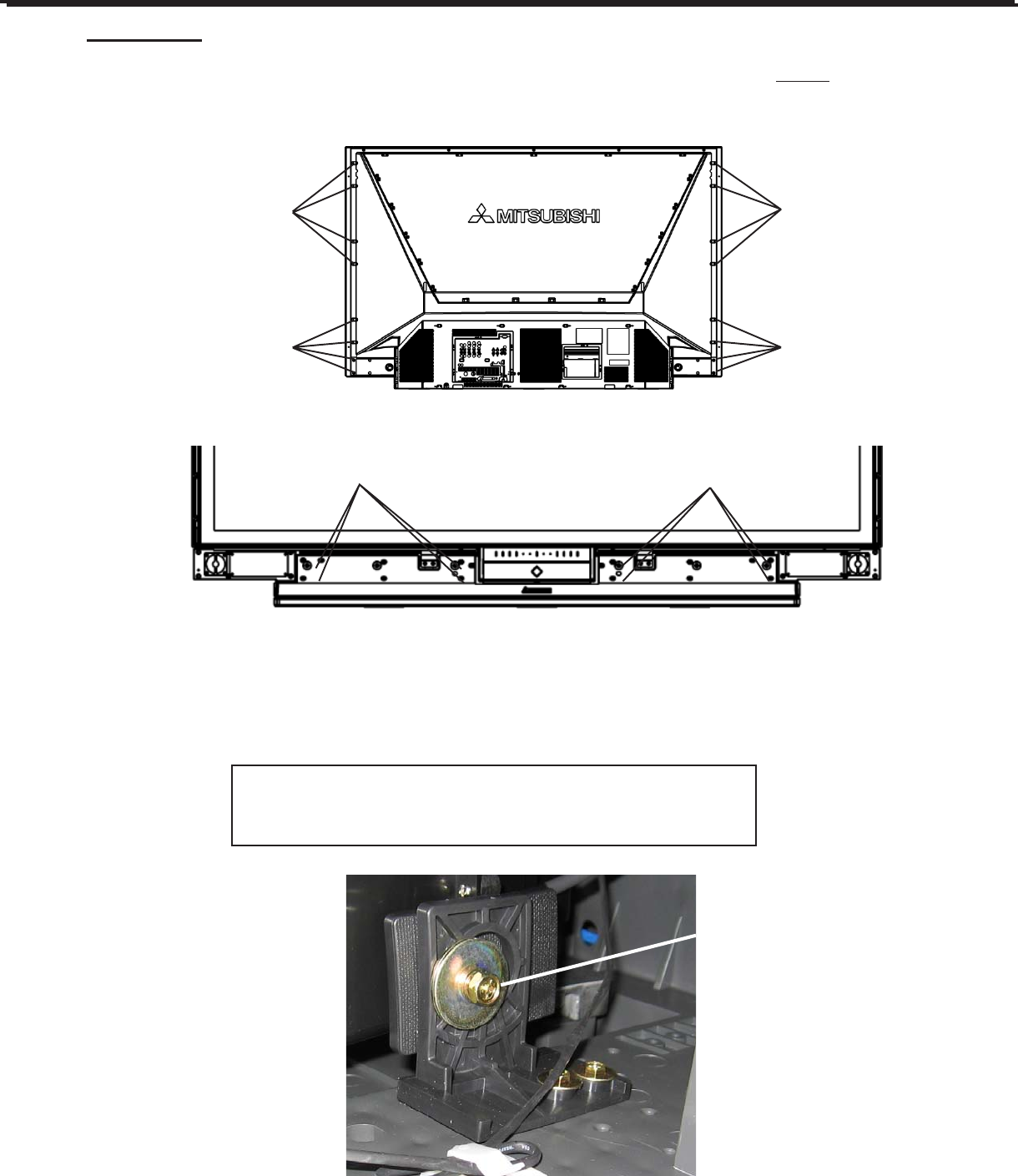
WARNING: DO NOT loosen [B-2] too far. The nut on
the other side may drop off. Then then Optical Engine must be
removed to re-install the nut.
[B-2]
Figure 2: 52” & 62” Side Locking Screw