


MODELS: WD-52627 / 52628 / 62627 / 62628 / 62827 / 62927 / 73727 / 73827 / 73927
Page 42
Prelminary
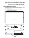
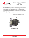
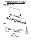
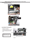
Mechanical Optical Engine Adjustments are made using the UNIT-ADJUSTER shown in Figure 1. The UNIT-ADJUSTER
is mounted under the Light Engine on the Engine Plate. It is accessed from the front of the set through the opening for
the Card Reader. Refer to the model specific Disassembly Instructions and remove the:
• Back Cover
• Speaker Grille
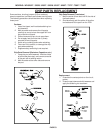
• Card Reader (Refer to page 43)
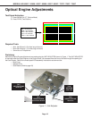
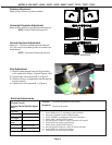
Optical Engine Adjustments
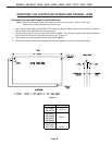
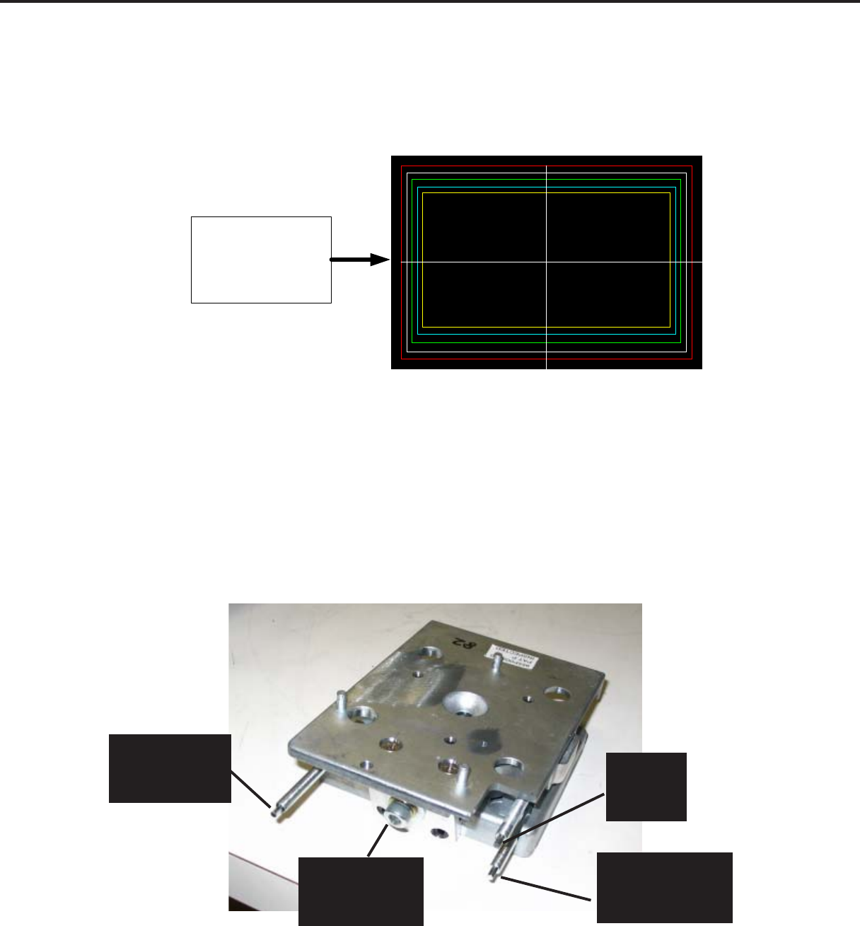
Test Signal Activation
1) Press “MENU-2-4-5-7” (Service Mode)
2) Press “REW” (Test Pattern).
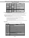
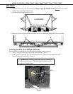
Red = 4% overscan
White = 5% overscan
Green = 6% overscan
Cyan = 7% overscan
Yellow = 10% overscan
Required Tools
• 4mm Hex Wrench (10 inches long minimum )
• 5mm Allen Wrench ( 10 inches long minimum)
• 10mm Hex or Phillips driver.
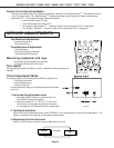
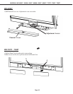
Figure 1: Unit-Adjuster
[A-1]
VERT. KEYSTONE
4mm Hex
[B-1]
LOCKING SCREW
5mm Allen Wrench
[A-3]
HORIZ. KEYSTONE
4mm Hex
[A-2]
ROTATION
4mm Hex