


-16-
4. CONNECTIONS
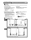
4.4 Measuring Input Terminals
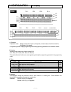
1 Measuring input terminals
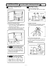
Make sure to turn off the power supply to prevent
an electric shock.
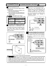
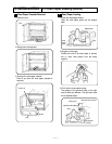
(1) Measuring input terminals are located on the
down left of the terminal board.
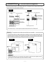
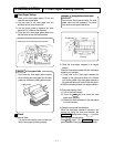
(2) For the connections to the input terminals, use
cables terminated by crimp style terminals with
insulation sleeves.
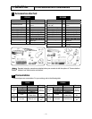
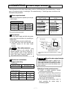
Input type Allowable input voltage
Voltage,
Thermocouple input
±10 VDC (range: ±2V or less)
±60 VDC (range: ±5V or more)
Resistance
thermometer input
±6 VDC
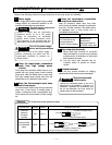
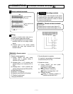
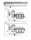
2 Connections of DC voltage (current) input
Use twisted cables for instrumentation as the
input cables for the purpose of suppressing noise.
For current inputs, mount shunt resistors
(Section 16.2) to the channels to be measured
before connections.
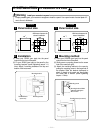
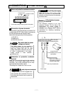
3 Connections of thermocouple inputs
Make sure to use thermocouple wires (or
extension wires) to the input terminals of your
recorder. If a copper wire is used halfway, a
noticeable measuring error occurs. Don’t use a
pair of thermocouple wires in parallel with other
instruments (controller, etc.), otherwise a
malfunction may occur.
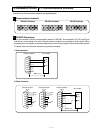
4 Connections of resistance thermometer inputs
Use a 3-core cable where each lead wire has an
equal resistance value. Don’t use one resistance
thermometer in parallel with other instruments
(controller, etc.).
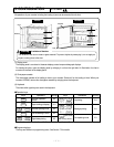
A high voltage may be applied to the measuring input terminals due to common mode noise. The
allowable noise value is 30 VAC or less, or 60 VDC or less. Make sure that the noise is lower than the
allowable value. Mount the terminal cover after connections for the purpose of preventing an electric
shock and to protect the input wires. In the case of thermocouple input, the mounting of the terminal cover
can reduce the reference junction compensation error.
Allowable input voltage
mark of measuring input terminals
Terminal cover
DC voltage input
1
2
3 4
(+)
(-)
Twisted cable for
instrumentation
1
2
3 4
Extension wire
Thermocouple
Red (+)
White (-)
1
2
3
4
Resistance thermometer
3-core cable
(Same diameter,
same length)
Note: Use a 3-core cable where
each lead wire has an equal
diameter and an e
q
ual resistance
A
B
B
Caution
Warning