


E-33
DV IN/OUT
AUDIO VIDEO
CH 1/3 CH 2/4
LINE
S -VIDEO
N
I
O
U
T
9PIN REMOTE
AUX
NTSC PAL
DC 12V
WARNING :
SHOCK HAZARD - DO NOT OPEN.
AVIS :
RISQUE DE CHOC ELECTRIQUE - NE PAS OUVRIR.
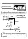
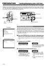
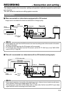
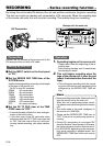
Player
DV terminal
Separately available
DV cable
Another VTR
Flow of
signal
DV terminal
Recorder
Monitor
DV IN/OUT
AUDIO VIDEO
CH 1/3 CH 2/4
LINE
S -VIDEO
N
I
O
U
T
9PIN REMOTE
AUX
NTSC PAL
DC 12V
WARNING :
SHOCK HAZARD - DO NOT OPEN.
AVIS :
RISQUE DE CHOC ELECTRIQUE - NE PAS OUVRIR.
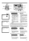
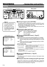
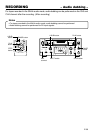
S-VIDEO IN
VIDEO OUT VIDEO LINE IN
AUDIO
IN
AUDIO
OUT
S-VIDEO
OUT
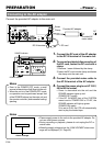
Player
Another VTR
Flow of
signal
Y/C(S) video cable
Monitor
Video cable
Audio cable
Recorder
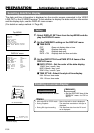
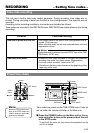
Memo
• When signals are input from the DV terminal, the sound recording mode of the recorder is the same
as that of the player.
• The Date and time data from the DV terminal will be recorded.
•To record the time code data from the DV terminal, set the DV TC DUP. item of the TIME CODE
menu to ON. (
☞
Page 58)
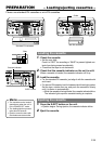
RECORDING – Connection and setting –
This chapter explains the connection, setting and operation methods required to use this unit
as a recorder.
This unit cannot be used as an editing system recorder.
Connection
Ⅵ When connected to a video device equipped with a DV terminal
Images can be recorded with almost no deterioration of image quality.
Ⅵ This unit is connected to a video device with no DV terminal (analog input) :
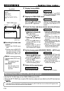
Memo
• When search pictures or low-quality video signals are input, video and sound output may be tempo-
rarily distorted. Please input stable signals via a TBC, etc.
• For analog input, use either Y/C(S) video cable or video cable. Set the front [INPUT] input video
signal selection switch according to the chosen cable.