


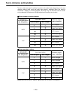
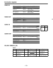
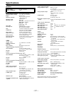
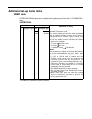
Connector signals
RS-232C REMOTE (25-pin D-SUB straight cable supported)
Pin No. Abbreviation
Circuit
Description
1
FRAME GROUND
Protective ground Frame ground
2
T×D
Transmitted data
Receives data from the PC.
3
R×D
Received data
Sends data to the PC.
4
RTS
Request to send
Shorted with pin 4.
5
CTS
Clear to send
Shorted with pin 5.
6
DSR
Data set ready
Positive power output after communication enable
status
7
GND
Signal ground
Signal ground
20
DTR
Data terminal ready
No processing
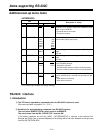
•
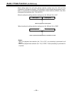
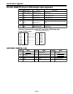
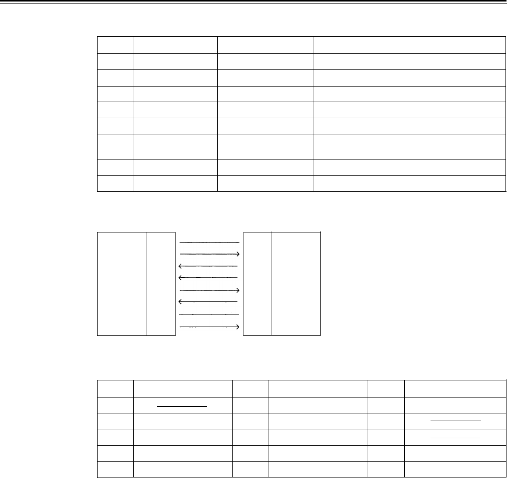
Example of connections with controller (PC) using a 25-pin D-SUB straight cable
PC end (D-SUB 25 pins)
VTR end (D-SUB 25 pins)
FG
1
T×D
2
R×D
3
RTS
4
CTS
5
DSR
6
GND
7
DTR
20
1
2
3
4
5
6
7
20
FG
T×D
RxD
RTS
CTS
DSR
GND
DTR
ENCODER REMOTE (15P)
Pin No. Signal
Pin No. Signal Pin No.
Signal
1
6
SYSTEM H
11
RET GND
2
SET UP
7 SYS.SC COARSE (2)
12
3
C LEVEL
8
–12V
13
4
GND
9 HUE
14
SYS.SC FINE
5
+12V
10
VIDEO LEVEL
15
SYS.SC COARSE (1)
–50–