


49
48
E
N
G
L
I
S
H
CQ-D5501U
48
47
E
N
G
L
I
S
H
CQ-D5501U
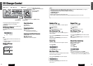
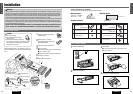
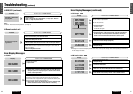
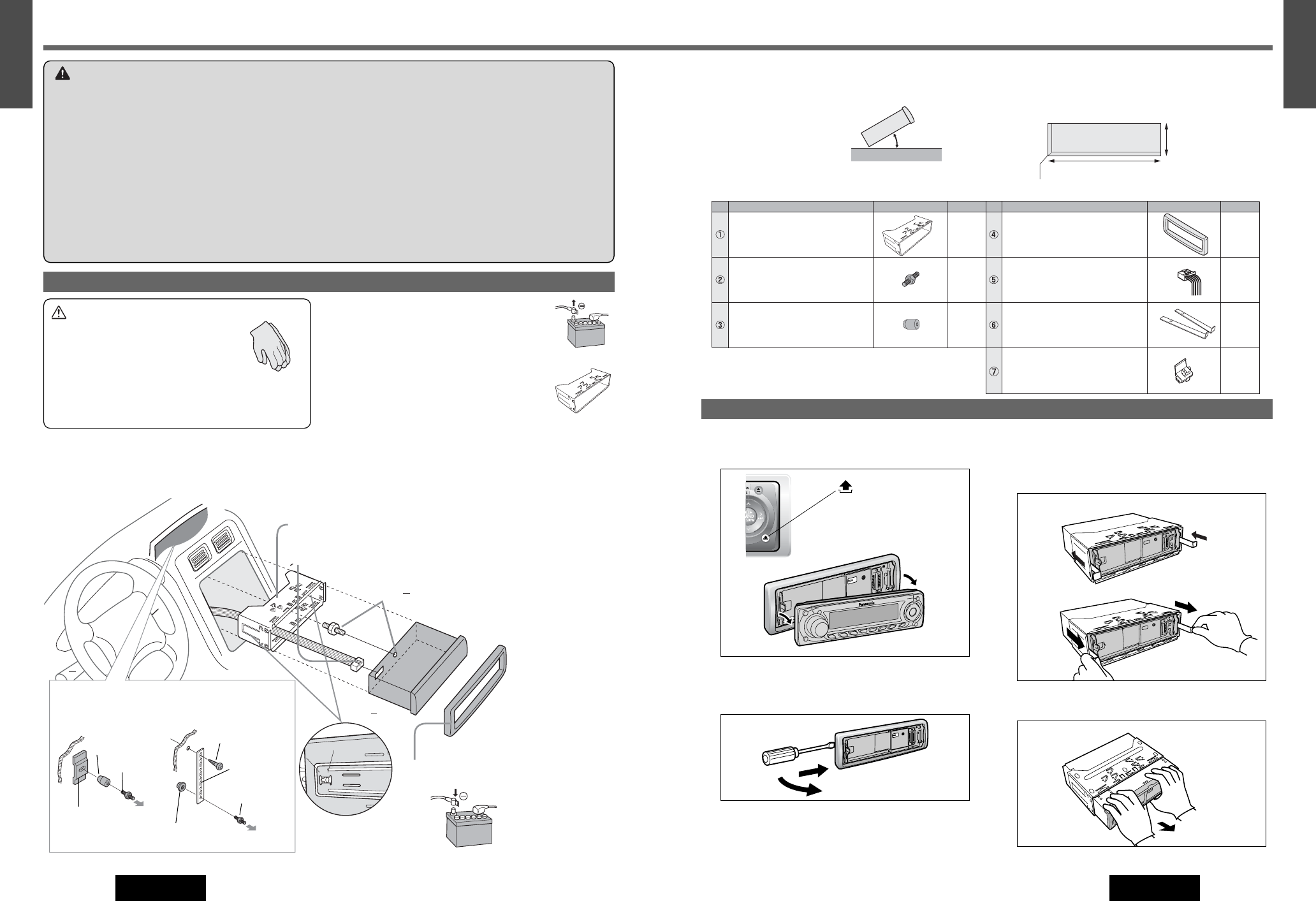
Installation
53 mm
182 mm
4.5 mm – 6.0 mm
0 – 30°
Consult a professional for installation.
Verify the radio using the antenna and speakers before installation.
Mounting Angle Mounting Space
side to side : horizontal
front to rear : 0 – 30°
e
2
3
4
5
6
4
w
4
4
w
q
1
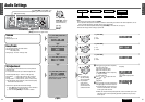
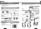
Remove the cable from the battery
negative terminal.
2
Mounting collar q insertion.
Bend appropriate tabs to secure the
unit without backlash.
3
Connection of power connector t.
4
Main unit securing
q Screw the mounting bolt w into the main unit.
w Secure to the fire wall.
e Snap the right and left springs into each hole.
5
Trim plate r mounting
6
Battery Cable reconnection
Using the rubber bushing
e
Using the rear support strap
(Option)
Clank!
Snapping Point
Securing to fire wall
Rubber Bushing
e
Tapping screw (Option)
3 mm ø
Rear support
bracket
(supplied with car)
Mounting Bolt
w
Mounting Bolt
w
Rear support
strap (Option)
To the unit
Caution
¡ Wear gloves for safety
¡ Make sure that wiring is completed
before installation.
¡ When this unit is installed in dashboard,
ensure that there is sufficient air flow around the unit to
prevent damage from overheating, do not block any
ventilation holes on the unit.
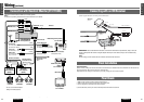
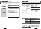
How to install the unit
Remove Mounting Collar q and Trim Plate r from the
main unit temporarily, which are already mounted at ship-
ment.
1
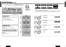
Remove the face plate.
2
Remove the trim plate r.
3
Lock release
q Insert the lock cancel plate y until you hear a click.
w Pull the main unit.
4
Pull out the unit with both hands.
w
q
w
q
e
w
q
How to remove the unit
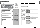
Supplied Hardware
1
1
1
1
2
1
Mounting Collar
Mounting Bolt (5 mmø)
Rubber Bushing
Trim Plate
Power Connector
Lock Cancel Plate
*
1
Clip Connector
No. Diagram
Q'ty
Item
No.
Diagram
Q'ty
Item
*
*
*
* w, e, y and u consist of a set. (YEP0FZ5724)
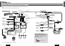
Warning
❐
This installation information is designed for professional installers with knowledge of automobile electrical safety sys-
tems and is not intended for non-technical, do-it-yourself individuals. It does not contain instructions on the electrical
installation and avoidance of potential harm to air bag, anti-theft and ABS braking or other systems necessary to install
this product. Any attempt to install this product in a motor vehicle by anyone other than a professional installer could
cause damage to the electrical safety system and could result in serious personal injury or death.
❐ If your car is equipped with air bag and/or anti-theft systems, specific procedures may be required for connection and
disconnection of the battery to install this product. Before attempting installation of this electronic component against
the manufacturer’s recommendation, you must contact your car dealer or manufacturer to determine the required proce-
dure and strictly follow their instructions.
FAILURE TO FOLLOW THE PROCEDURE MAY RESULT IN THE UNINTENDED DEPLOYMENT OF AIR BAGS OR ACTIVA-
TION OF THE ANTI-THEFT SYSTEM RESULTING IN DAMAGE TO THE VEHICLE AND PERSONAL INJURY OR DEATH.
(YEFC05652)
(YEFX0217263)
(YEAJ012851)
182 mm {7
5
/
32
”}
53 mm {2
3
/
32
”}
4.5 mm - 6 mm
Hexagonal nut
(Option)