


51
50
E
N
G
L
I
S
H
CQ-D5501U
50
49
E
N
G
L
I
S
H
CQ-D5501U
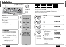
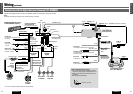
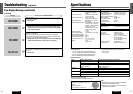
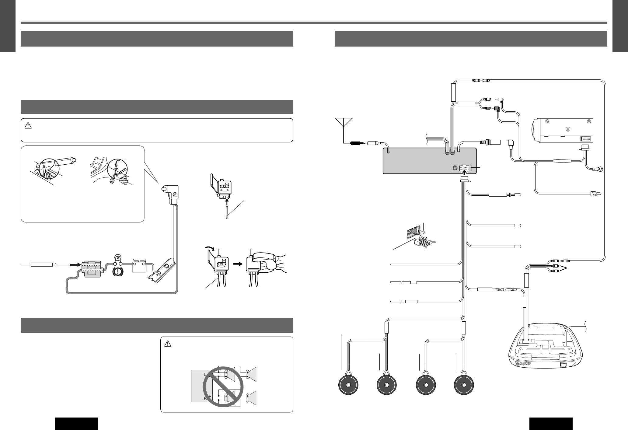
Wiring
Connection with the CD Changer and the Overhead Monitor (CY-VH9300U)
Connection with CD changer and the overhead monitor (option, CX-DP880, CY-VH9300U).
Note:
¡Refer to the operating instructions for the connected devices, in addition.
VIDEO-CONT
ACC
BATTERY 15A
FRONT SP
REAR SP
PARKING BRAKE
+
-
+
-
VIDEO-OUT
CH/AUX-IN
+
-
+
-
1
3
2
VIDEO CONT
VTR1 – IN
Ground Lead
To a clean, bare metallic part of the car
chassis.
Parking Brake Lead
(Blue/yellow stripe)
Be sure to wire the parking brake
for safety and preventing accident.
Power Lead
To ACC power, + 12 V DC
Video Control Lead
(Green/yellow stripe)
Battery Lead
To the car battery, continuous + 12 V DC
(Black)
(Yellow)
(Red)
CQ-D5501U
DVD Player/Receiver
CX-DP880 (Option)
CD Changer Unit
Antenna Cable
Antenna
Power Connector
Ground Lead
To a clean, bare metallic
part of the car chassis.
Extension Cord
(DIN/BATT/RCA/GND)
(R)(Red)
(L)(White)
CH/AUX-IN
RCA Cord
VIDEO-OUT (Yellow)
RCA Cord
VIDEO-IN
(Yellow)
Not used
CY-VH9300U (Option)
Over Head Monitor
Battery Lead
To the car battery, contin-
uous + 12 V DC
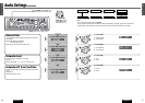
Rear Speakers
CJ-DA6920U
Front Speakers
CJ-DA1600U
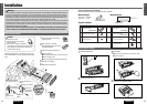
¡ Exclusively operated with 12 V battery with negative (–) ground.
¡ Connect the power lead (red) very last.
¡ Connect the battery lead (yellow) to the positive (+) terminal of the battery or fuse block terminal (BAT).
¡ Strip about 5 mm {
1
/
4
”} of the lead ends for connection.
¡ Apply insulating tape to bare leads.
¡ Secure loosened leads.
Before Wiring
*Fuse (15 A) Refer fuse replacement to your near-
est authorized Panasonic Servicenter. Do not try fuse
replacement by yourself.
Fuse*
DIN Cord
Motor Antenna Relay Control Lead
(Blue)
Left
Left Right
Right
Green/black stripe
Violet/black
stripe
White/black
stripe
Gray/black
stripe
Green
Violet
White
Gray
External Amplifier Control Power Lead
(Blue/white stripe)
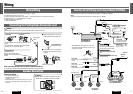
Connect as follows
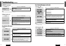
¡ Use ungrounded speakers only.
Allowable input: 50 W or more
Impedance: 4 – 8 Ω
¡ Distance between speaker and amplifier: 30 cm {12”} or more
¡ Do not use a 3-wire type speaker system having a common
earth lead.
Caution
¡ Do not connect more than one speaker to one set of
speaker leads. (except for connecting to a tweeter)
Speaker Connection
–
+
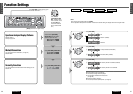
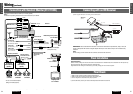
PARKING BRAKE
The parking brake switch position varies with the car
model.
For details on the exact location of the parking brake
switch in your car, contact your dealer.
q Attach a Clip Connector u to the end
of the parking brake connection lead.
w The Clip Connector u is connected to
the power source side lead of the park-
ing brake.
Connecting the Parking Brake Connection Lead
Hand brake Foot brake
Parking Brake Lead
(Blue/yellow stripe)
When the parking brake lever is
engaged, the unit is grounded by the
chassis.
Parking brake
switch
Car chassis
Battery
Brake light
Clip Connector u
Parking Brake Lead
(Blue/yellow stripe)
Power source side lead
Caution
¡ For safety, be sure to ask your nearest professional installer to do this connection.
When connecting this unit to the rear monitor (overhead/headrest):
¡ The parking brake lead and grand lead should be connected to the same terminal.