


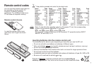
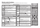
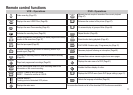

NV-VP30
NV-VP30
REC
EXT LINK CH
TIMER REC
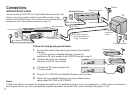
Note:
[RGB] means separate Red/Green/Blue colour signals. If you connect a TV equipped with RGB
input capability to the AV1 socket on this VCR, and a decoder equipped with RGB output
capability to the AV2 socket, RGB signals will pass through the VCR to the TV when the VCR is
in standby mode. The RGB signals cannot be recorded or produced by this VCR.
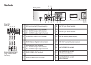
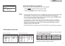
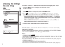
To connect this VCR to a decoder, make the connections shown in the illustration below.
For the connection to the TV, see page 13.
For details about the connection, also read the operating instructions of the decoder. Be sure to
keep the VCR, TV and decoder disconnected from mains until you have finished all connections.
Use a 21-pin scart cable to connect
the decoder to the VCR'sAV2 21-
pin scart socket
1
2
3
Connect a 21-pin scart cable to the AV2 21-pin scart socket on the VCR and
to the 21-pin scart socket on the decoder.
Connect the decoder’s mains lead to an AC mains socket.
Set to . For details, see page 33.
AV2 DECODER
Connecting the VCR to a Decoder
LP
Video
Audio
LR
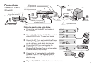
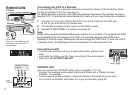
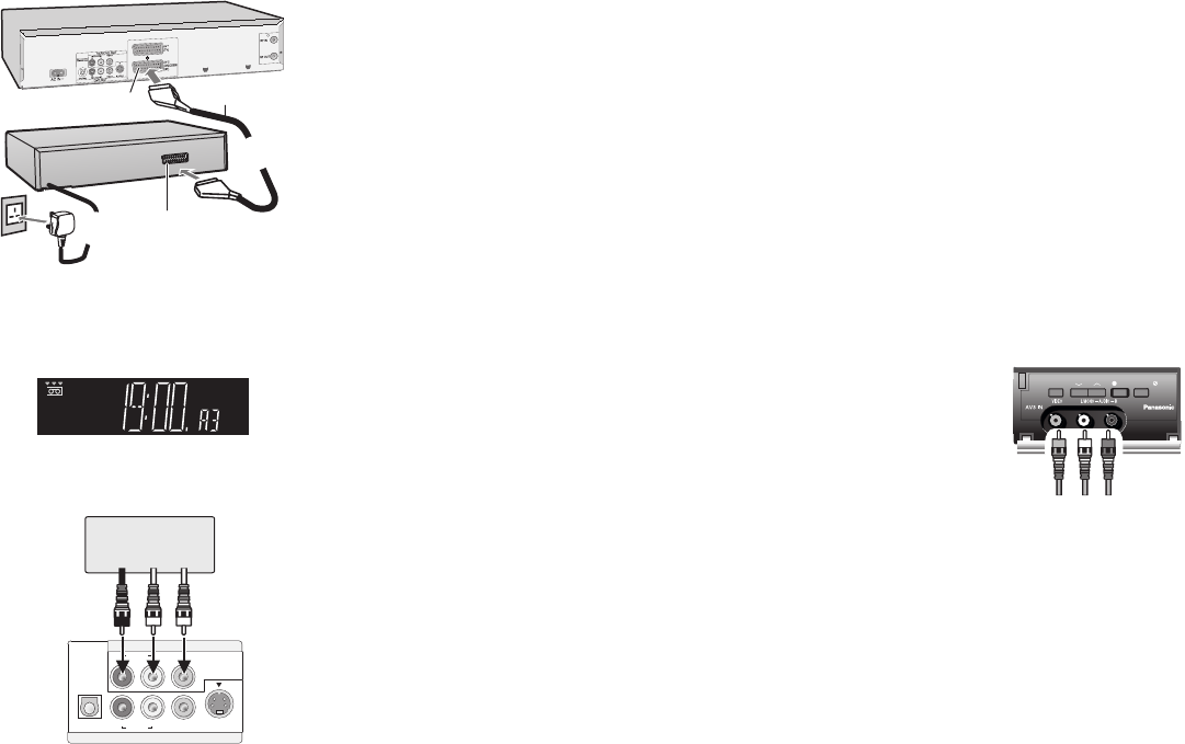
Connecting to AV3
!
Connect your external unit (e.g. a video camcorder) with the front
input.
Just seize the L/Mono port for mono recording of the audio signal.
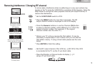
Select A3 with .
!
!
AV INPUT SELECT
External units
14
2
21-pin Scart
cable
21-pin Scart socket
To AC
Mains socket
Decoder
(AV2)
1
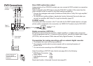
VCR/DVD
VCR/DVD OUT
DVD OUT
OPTICAL AUDIO VIDEO S VIDEO
RL
AUDIO VIDEO
RL
DIGITALAUDIO OUT
(PCM/BITSTREAM)
Amplifier or TV set
(example)
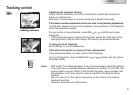
VCR/DVD OUT
You can connect the VCR/DVD direct with an Amplifier or TV set.
Connect the analogue audio output (L/white and R/red) with a “Dolby Pro Logic
amplifier”, for example.
To avoid sound quality problems, deactivate function Advanced Surround when
you connect an amplifier with Dolby Pro Logic functionality (page 57).
!
!
Rear of
VCR/DVD