


10
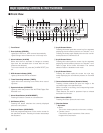
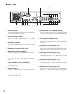
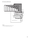
■ Rear View
q Power Cooling Fan
Prevents the temperature of the recorder from rising. Do
not block the ventilation openings.
w AC Power Connector (AC IN)
Connect the supplied power cable to this AC power
connector.
e Power Switch (POWER)
This switch turns the power of the disk recorder on and
off.
r Signal Ground Terminal (SIGNAL GND)
t Mode Selection DIP switches (MODE)
This 2-bit DIP switch is used for setting the terminal sys-
tem. Refer to DIP Switch Setting for details.
y Data Port (DATA)
This port is for data communication with external
devices.
u 10Base-T/100Base-Tx Port (10/100BASE-T)
This port is used to exchange control data with Ethernet
via an Ethernet Hub.
i Copy Port (COPY1)
This port is used to connect an external hard disk to
back up the data recorded on the hard disks.
o Serial Data Port (SERIAL)
For servicing purpose only.
!0 Terminal/Control Port (TERMINAL/CONTROL)
This port controls terminal inputs 1-8 and alarm outputs
1-3. It is also used to connect component cameras with
the RS485 protocol feature.
!1 VGA Output Port (MONITOR (VGA))
When a VGA monitor is connected to this port, the
same image as supplied from the video output terminal
is obtained.
!2 Video Output Connector (VIDEO OUT)
Spot live, split-screen, and playback pictures are output
from this BNC connector. All menu settings and screen
display information are also output from this connector.
!3 Video Input Connectors (VIDEO IN 1-8)
System cameras or component cameras are connected
to these BNC connectors. A 75 Ω termination is made
unless the video output terminal is connected.
!4 Audio Input Connectors (AUDIO IN 1-8)
These are used for BNC standard jacks. Each of them
accept an unbalanced –10 dBV, 22 kΩ line input audio
signal supplied from an external device.
!5 Audio Output Connector (AUDIO OUT)
This is used for a BNC standard jack that supplies an
unbalanced –10 dBV, 22 Ω line output audio signal to
an external device.
MODE
DATA
10/100BASE-T
COPY1
SERIAL
MONITOR(VGA)
TERMINAL/CONTROL
AUDIO OUT
VIDEO OUT
AC IN
SIGNAL GND
POWER
1
1
2
2
3
3
4
4
5
5
6
6
7
7
8
8
ON
OFF
!
4
!
5
e w
!3!2!1!0oiuytq r
VIDEO IN
AUDIO IN