Chapter 2 – Installation
11
E-AC Drive Hardware Installation Guide
INSTALLATION PROCEDURE
In the following installation procedure, we assume you are using a
Compumotor motor with your E-AC Drive. If you are using a non-
Compumotor motor, consult Appendix A – Using Non-Compumotor Motors
for information you may need during the following installation steps.
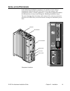
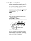
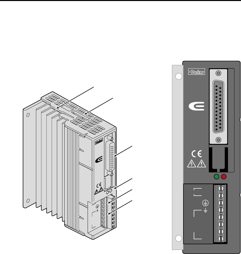
The next drawing shows locations and names of the various connectors,
switches and LEDs that you will encounter during the installation proce-
dure.
11
11
23
23
9
21
21
17
17
16
16
15
15
2
14
14
1
RESET+
RESET+
RESET
RESET
–
FLT C
FLT C
FLT E
FLT E
SD
SD
–
SD +
SD +
DIR
DIR
–
DIR +
DIR +
STEP
STEP
–
STEP +
STEP +
MOTOR
N
A +
A -
B +
B -
120
V
SERIES
PWR/FLT
C
om
pu
m
otor
DIP Switches
I/O Connections
Status LEDs
AC Power
Motor Power
Heatsink
SERIES
DRIVE I/O
MOTOR
PWR/FLT
Compumotor
L1
N
A +
A -
B +
B -
120V
Component Locations


