Chapter 2 – Installation
21
E-AC Drive Hardware Installation Guide
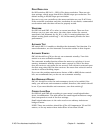
DRIVE RESOLUTION
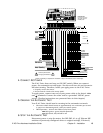
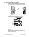
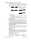
Set DIP switches SW1-#2 — SW1-#5 for drive resolution. There are six-
teen settings, which range from 200 to 50,800 steps per revolution. The
default setting is 25,000 steps per revolution.
Be sure to set your controller to the same resolution as your E-AC Drive.
If the controller resolution and drive resolution do not match, commanded
accelerations and velocities will not be properly scaled.
WAVEFORM
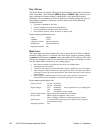
Set SW1-#6 and SW1-#7 to select a current waveform. There are four
choices: one is a pure sine wave; the other three reduce the current
waveform’s 3rd harmonic by 4%, 6%, or 8%. In most applications, the
default setting (both switches off = -4% 3rd harmonic) provides the best
performance.
AUTOMATIC TEST
DIP switch SW1-#1 enables or disables the Automatic Test function. For
more information, see the Automatic Test section earlier in this chapter.
AUTOMATIC STANDBY
SW1-#8 should be off if you do not use automatic standby. Turn this
switch on to use automatic standby.
The automatic standby function allows the motor to cool when it is not
moving. Automatic standby reduces motor current by 50% if the drive
does not receive a step pulse for one second. Full current is restored upon
the first step pulse that the drive receives. Be aware that reduced current
results in reduced holding torque.
If you use the position maintenance feature of 6K or 6000 Series control-
lers, we recommend that you do not use automatic standby.
ANTI-RESONANCE DISABLE
SW1-#1 should be on for the anti-resonance circuit to be enabled. Nor-
mally, you will want anti-resonance enabled; therefore, this switch should
be on. If you must disable anti-resonance, turn this switch off.
CURRENT LOOP GAIN
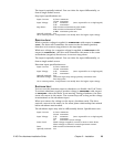
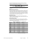
Set SW2-#2 and SW2-#3 according to your motor’s small-signal induc-
tance, in millihenries. The table shows the small-signal inductance range
that corresponds to each of the four settings.
Small-signal inductance is the value read on an ordinary inductance
bridge or meter.
NOTE: These two switches should be off for all Compumotor VS and OS
motors, or for any motor whose inductance is less than 32 mH.


