6
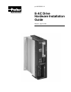
E-AC Drive Hardware Installation Guide Chapter 1 – Introduction
E-AC DRIVE – DESCRIPTION
The E-AC Drive is a microstepping drive that runs two-phase step motors.
It operates directly from 120VAC power; no separate DC power supply or
transformer is required.
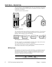
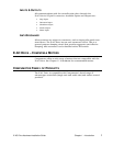
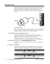
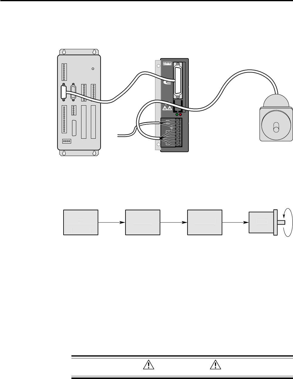
A typical system is shown below.
To AC
Power Source
Controller
Motor
E-AC Drive
SERIES
DRIVE I/O
MOTOR
PWR/FLT
Compumotor
L1
N
A +
A -
B +
B -
120V
System Components
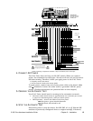
The controller sends step and direction signals to the drive. For each step
pulse it receives, the drive will commutate the motor to increment rotor
position. This is shown in the next drawing.
C
ontrolle
r
E-A
C
Driv
e
M
o
t
or
M
o
t
or
C
urrent
s
Ste
p
P
u
l
ses
Hi
g
h Leve
l
C
ommand
s
Host Com
p
ute
r
o
r
Pro
g
rammabl
e
C
ontrolle
r
Block Diagram of E-AC Drive System
The host computer or programmable controller may or may not be neces-
sary, depending upon the controller’s capabilities.
The motor can be wired in series or parallel; the amount of current the
drive sends to the motor is set by DIP switches.
DIP SWITCHES
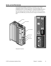
DIP switches are located on top of the E-AC Drive, accessible through an
opening in the top of the cover. During the installation procedure, the
user sets these DIP switches to configure the drive for motor current,
resolution, waveform, and other functions.
CAUTION
Remove power before changing DIP switches


