Chapter 2 – Installation
27
E-AC Drive Hardware Installation Guide
tions in the mounting structure that can cause fatigue in structural
members. A mechanical engineer should check the machine design to
ensure that the mounting structure is adequate.
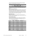
WARNING
Improper motor mounting can jeopardize personal safety, and
compromise system performance.
For Compumotor motor dimensions, see Select a Motor earlier in this
chapter.
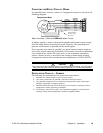
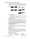
MOTOR TEMPERATURE & COOLING
The motor’s face flange is used not only for mounting; it is also a heatsink.
Mount the face flange to a large thermal mass, such as a thick steel or
aluminum plate, which should be unpainted, clean, and flat. Heat will be
conducted from inside the motor, through the face flange, and dissipated
in the thermal mass. This is the best way to cool the motor. You can also
use a fan to blow air across the motor for increased cooling, if conduction
through the flange does not provide enough cooling.
MOTOR MODIFICATIONS
Modifying or machining the motor shaft will void the motor warranty.
Contact a Compumotor Applications Engineer (800-358-9070) about shaft
modifications as a custom product.
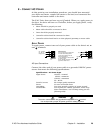
EXTENDING MOTOR CABLES
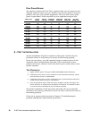
If you need to extend Compumotor motor cables beyond the standard
10 feet (3 m), consult the table below for recommended wire sizes. Cables
longer than 50 feet (15 m) may degrade system performance. Do not
extend cables beyond 200 feet (61 m).
Max. Current Less than 100 ft. (30 m) 100 – 200 ft. (30 – 60 m)
Motor Type (amps) Size: AWG mm
2
AWG mm
2
OS2HBS 1.70 22 0.34 20 0.50
OS2HBP 3.39 20 0.50 18 0.75
OS21BS 1.82 22 0.34 20 0.50
OS21BP 3.50 20 0.50 18 0.75
OS22BS 2.38 22 0.34 20 0.50
OS22BP 3.50 20 0.50 18 0.75
VS12BS 1.03 22 0.34 20 0.50
VS12BP 2.04 22 0.34 20 0.50
VS13BS 1.03 22 0.34 20 0.50
VS13BP 2.04 22 0.34 20 0.50
VS21BS 2.27 22 0.34 20 0.50
VS21BP 3.50 20 0.50 18 0.75
VS22BS 2.04 22 0.34 20 0.50
VS22BP 3.50 20 0.50 18 0.75
VS23BS 2.04 22 0.34 20 0.50
VS23BP 3.50 20 0.50 18 0.75
VS31BS 3.05 22 0.34 20 0.50
VS31BP 3.50 20 0.50 18 0.75
VS32BS 3.16 22 0.34 20 0.50
VS32BP 3.50 20 0.50 18 0.75
S: Series Configuration P: Parallel Configuration Rated current in wire sizes shown may result in a maximum
temperature rise of 10°C (18°F) above ambient.


