


18 C623M-C (3/05)
Hardware Setup
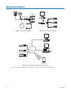
BASIC CONNECTIONS
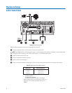
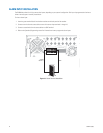
Figure 8.
Basic Connections
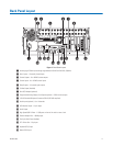
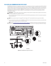
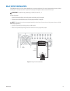
Make the following connections on the rear of the recorder. Refer to Figure 8.
ᕡ
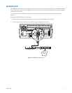
Connect the appropriate power cord to the back of the unit and to a power source.
ᕢ
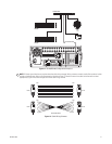
Connect the mouse to the top PS/2 input.
ᕣ Connect the keyboard to the bottom PS/2 input.
ᕤ Connect a VGA monitor (not supplied).
ᕥ Connect the cameras to the BNC connectors. Refer to Table A for video coaxial cable requirements. Connect power to the cameras.
NOTE: The DX8000 contains an autoranging power supply. It is recommended that the recorder be connected to an uninterruptible power
supply (UPS) capable of supplying 2 A for 120 VAC power systems or 1 A for 230 VAC power systems.
Table A. Video Coaxial Cable Requirements
Cable Type* Maximum Distance
RG59/U 750 ft (229 m)
RG6/U 1,000 ft (305 m)
RG11/U 1,500 ft (457 m)
*Minimum cable requirements:
75 ohms impedance
All-copper center conductor
All-copper braided shield with 95% braid coverage
When connecting cameras using these types of cable, use a
patch panel. Do not connect these cables directly to the
DX8000.
SPECTRA
VGA
CAMERA
KEYBOARD
MOUSE
ᕡ
ᕣ
ᕢ
ᕥ
ᕤ
POWER
CONNECTION