


C623M-C (3/05) 23
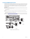
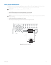
RELAY OUTPUT INSTALLATION
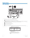
The DX8000 has either 8 or 16 relay outputs, depending on your system’s configuration. Each output is programmed to function as either a
normally open or normally closed circuit. A signal from a relay output will operate the device connected to the output.
To wire a relay output:
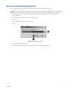
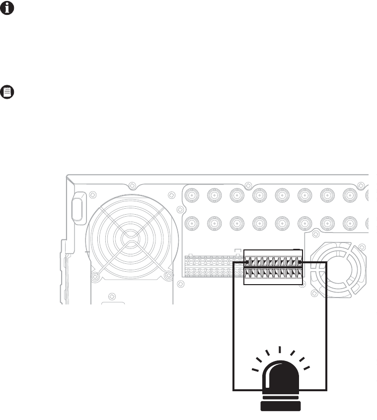
1. Insert the blue terminal blocks into the relay sockets on the back panel of the recorder.
2. Connect one wire from the device to one of the relay output terminals 1 through 16.
3. Connect a second wire from the relay device to a GND terminal.
4. Refer to the Operation/Programming manual for information on how to program relay outputs.
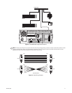
Figure 14. Relay Terminal Installation
IMPORTANT: The maximum relay power rating is 120 VAC, 0.5 A; 24 VDC, 1 A.
NOTE: Relay outputs do not have to correspond numerically to alarm inputs. All sensor input and relay output actions can be linked
through programming.
IN1 IN2 IN3 IN4 IN5 IN6 IN7 IN8 IN9
IN9 IN10 IN11 IN12 IN13 IN14 IN15 IN16
OUT16OUT15OUT14OUT13OUT12OUT11OUT10
OUT
9OUT9
OUT8OUT7OUT6OUT5OUT4OUT3OUT2OUT1
ALARM INPUTS RELAY OUTPUTS
1 2245678GND
910111213141516
1 2245678GND
910111213141516
9 10 11 12 13 14 15 16
CRT
RELAY
OUTPUT 1
GND