


12 C2601M-A (6/06)
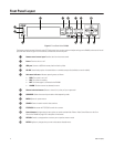
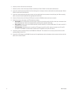
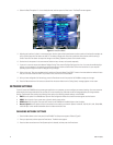
6. If desired, connect a VGA monitor to the VGA port.
7. If desired, connect a monitor that accepts S-Video to the SVHS port. Refer to Table A for video coaxial cable distances.
8. If you want to receive audio transmissions from the remote agent on a computer, connect an audio cable to the audio output jack. Refer to
Table A for video coaxial cable distances.
9. If you want to record audio along with video, connect up to four audio feeds from the cameras to the audio input jacks. Before recording
audio, consult your location’s applicable laws regarding audio surveillance.
10. Connect an Ethernet cable at the Ethernet (TCP/IP) port to connect the DX4000 to remote users across a network.
11. Connect alarm inputs, relay outputs, and PTZ connections as follows:
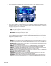
• Alarm inputs: You can have one alarm for each camera. Connect one alarm lead to the IN1, IN2, IN3, or IN4 input, and the other alarm
lead to the ground input. Alarms can be programmed for normally open or normally closed inputs.
• Relay outputs: Connect a relay to the normally open (NO), normally closed (NC), or common (COM) outputs. The relay is rated for I A
at 30 VDC or 0.5 A at 125 VAC.
• PTZ connections: Connect the leads for controlling a PTZ camera from the RX+ and RX- leads on the camera to the TX+ and TX-
connectors on the DX4000. To connect several cameras with PTZ capabilities, daisy-chain the cameras.
12. If necessary, connect a computer directly to the DX4000 with a DB9 cable. This connection is for use only by service technicians while
resolving problems with the unit.
13. Connect the 12 VDC adaptor to the DX4000. Connect one of the supplied power cords to the adapter, and then connect the other end of the
power cord to a source of power.