


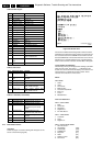
Diagnostic Software, Trouble Shooting and Test Instructions
EN 40 DVD763SA5.
5.9 Test Instruction Front Display and Audio/
Video Board
These test instruction is designed specifically for SACD 2002
single disc models which has the following outputs:
• 6 Channel Audio output
• Coaxial / Optical digital output
• CVBS
• Component output YUV
• SVHS
• Double SCART output
• Front Display
5.9.1 General
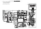
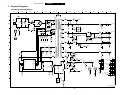
• All the waveforms measurement carried out in these test
instruction will be base on the testpoint indicated in the
A/V Board and Front Display schematic diagram in the
Service manual.
• Impedance of the measuring-equipment should be > 1MΩ
• Most of the tests can be done using either the Diagnostic
software “ Player script” which can be found in the chapter
“Diagnostic Software description and troubleshooting” or
the Menu interface using the Service PC with a terminal
emulation program ( e.g. Window Hyperterminal ) where it
is possible to control the execution of the Diagnostic Nuclei
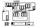
• Setup for the measurement will be done in set level with all
modules connected as shown in the Wiring Block diagram.
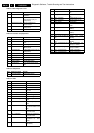
5.9.2 General Start-Up Measurement
Supply Check:
Before starting the measurement,ensure that all power supply
are connected to the A/V and Front Display board via
conn.1420 and 1127 respectively.
Clock Check
Ensure the present of the clock to the DAC and the slave µP.
Audio Mute Check
Measure the Audio mute voltage input at pin 22 of connector
1421
To toggle between ON and OFF,use the following commands:
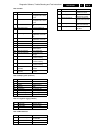
5.9.3 Audio DAC And Amplifier
Ensure that the Audio mute signal is OFF
To check the DAC and buffer amplifier,send the following
commands.
The audio signal ( sine or pink noise ) will also be present on
the digital output ( SPDIF ).This can be checked by connecting
digital signal to an amplifier with digital input.
Check the I2S and audio signal at the following testpoints:
All waveforms can be refered to the A/V board schematic
diagram.
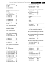
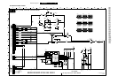
5.9.4 Video Output And Buffer Amplifier
Check DC output-level at all video cinch output : 1.0V DC ±
10%
Generate a color bar using the following software commands:
Check the video outputs at the following testpoints:
ll waveforms can be refered to the A/V board schematic
diagram.
5.9.5 Play and 16/9 Detection
Check DC voltage at S-VIDEO-CHROMA output (pin 4) with a
6k8 ohm load and SCART connector 1403 (pin 16) and change
the SCART0 and SCART1 input using the following
commands:
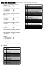
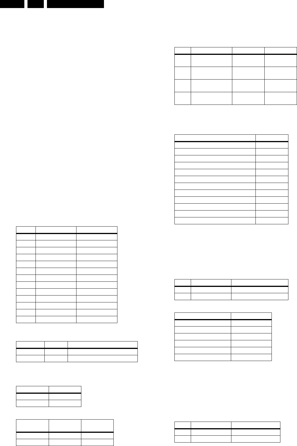
Pin nr. A/V Board Front Display
Voltage Conn. 1420 Conn. 1127
1 +3V3_Power -
2 +3V3_Power -
3GND -
4 +12V_Power -
5 +12VSTBY -
6GND+5VSTBY
7 +5VSTBY +12V_Power
8 GND -32V_Power
9-12V_Power -
10 GND -
11 -32V_Power -
12 -
Clock Name Testpoint Frequency
PCM_CLK I117 11.2896MHz ± 0.02% tolerance
XOUT S1 8MHz ± 0.2% tolerance
Status Value
AudioMuteOn HIGH (>3V)
AudioMuteOff LOW (<3V)
Ref.#
Command
Name Remarks
19a AudioMuteOn Audio Mute On
19b AudioMuteOff Audio Mute Off
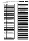
Ref.# Command Name Remarks Audio output
21a AudioSineOn Audio Sine
signal ON
Sine,1Khz on
stereo
---- Press stop button Audio Sine
signal OFF
No waveform
20a AudioPinkNoiseOn Audio
Pinknoise ON
Pink Noise on
6 channels
20b AudioPinkNoiseOff Audio
Pinknoise OFF
No waveform
Name Testpoint
PCM_LRCLK I115
PCM_SCLK I116
PCM_CLK I117
SDT1 I114
SDT2 I112
SDT3 I110
DIG_OUT I499
STEREO L/R OUT I330 / I333
FRONT L/R OUT I336 / I339
SURROUND L/R OUT I348 / I351
CENTRE OUT I345
SUB WOOFER L/R OUT I342
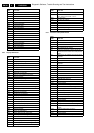
Ref.# Command Name Remarks
23a VideoColDencOn Colour DENC ON
23b VideoColDencOff Colourbar DENC OFF
Name Testpoint
GREEN_Y I502
BLUE_U I491
RED_V I494
CVBS out_Mono I480
C_Mono I483
Y_Mono I482
Ref.# Command Name Remarks
25a VideoScartLo Sends out 0V ± 0.5V
25b VideoScartMi Sends out 6V ± 10%