


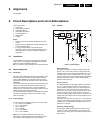

Circuit Descriptions and List of Abbreviations
EN 72 DVD763SA9.
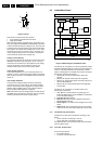
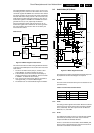
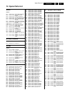
Clock Factory
One clock factory is implemented to support all clocks required
by the Furore 2. The various master clock, which depends on
whether SACD is present, is used for SD4.00_SA_CH. The
clock factory of SD4.00_SA_CH is showed in Figure 8-2.
Figure 9-7 Block diagram clock factory
For the SACD player, the clock system is a DAC master clock
system. For non-SACD player, the clock system is a mono
board master clock system.
The Furore 2 supports clock 256*FS/384*FS/512*FS. The
most convenient value in the market is 16.9344 MHz (384*FS,
FS=44.1KHz). Therefore, the master clock on the
SD4.00_SA_CH mono board is the 384*FS coming from the A/
V board. The 384*FS (16.9344 MHz) from the DAC clock, must
always be present. It is buffered before it is sent to the Furore
2 and the rest of the clock factory. The IC S612G delivers a 27
MHz system clock.
The Furore 2 and Sti5580/Sti5588 (Video) use this clock. It is
used to derive the PCM audio clocks 256*FS by the
MK2703STR. This IC is also used to buffer the incoming 27
MHz clock.
The communication between the Sti55xx and the Furore 2 is
asynchronous.
To support non-SACD playback, an on-board 27MHz oscillator
delivers the master clock for SD4.00_SA_CH mono board.
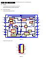
Miscellaneous
Most general IO ports are connected directly to the module
interface. Compared with the SD3.0 module, some on-board
circuits are removed, as it made more sense (and more cost
effective) to implement these circuits externally.
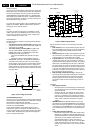
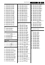
SCART Status Signal
The SCART0 and SCART1 signals are directly available at the
module interface, where the 0_6_12V signal is generated. See
table below:
Table 9-1 0_6_12V SCART status truth table
Mute
The audio MUTE signal (active 'high') is directly available at the
module interface.
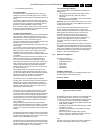
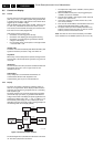
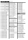
Service
Figure 9-8 Service Port Buffer
The service port (see diagram M5) is simplified to reduce cost.
The unused RTS and CTS lines are no longer connected. A
transistor buffer (item 7508) is used instead of the Schmitt
Trigger buffer (item 7501).
The overall loading and driving capability of the RS-232
emulator port is not greatly changed. However, as a
precaution, the Schmitt Trigger circuit remains in the layout as
an optional implementation.
This SD4.0SA_CH has the same ComPair connector as in
previous DVD generations. Flashing of the application-SW is
not possible with the ComPair cable, except with a CD-R disc.
For sets with Mask-ROM software, replace it with a
programmed Flash (available via your Philips Service
organisation).
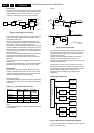
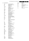
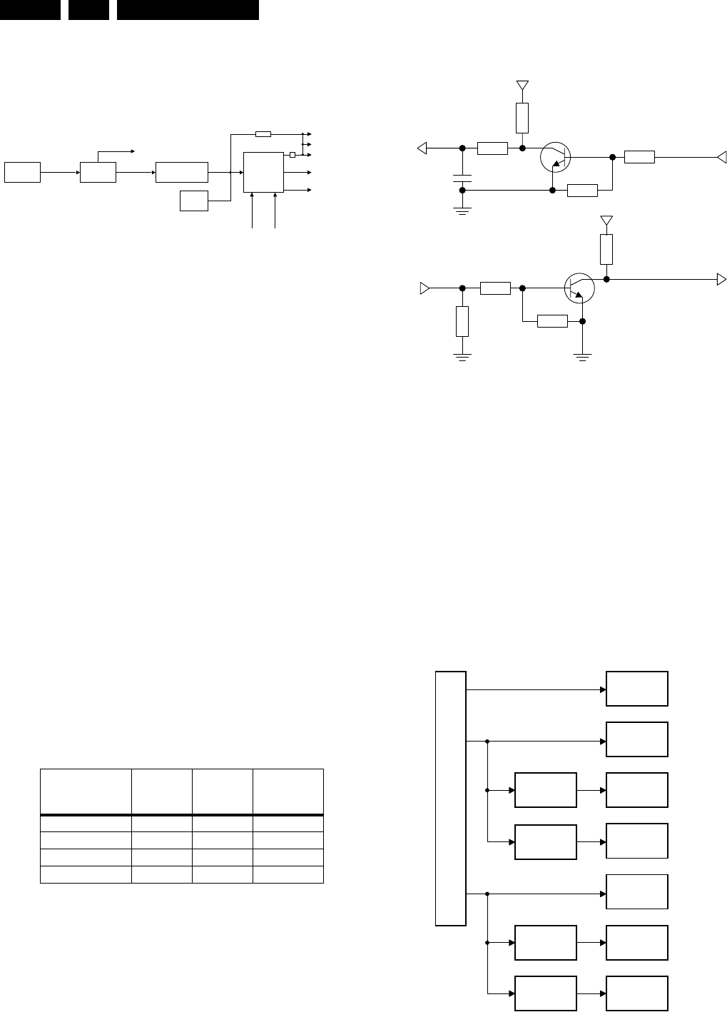
Power Supply (diagram M7)
Figure 9-9 Mono Board Power Supply Block Diagram
The main power supplies to the module are 3.3V, 5V, and 12V
(input via connector 1703).
Function PIO3_6
(SCART0)
PIO3_7
(SCART1)
0_6_12V
(at SCART
connector)
TV display 1 1 0V
TV display 0 1 0V
16:9 aspect ratio 1 0 +6V
4:3 aspect ratio 0 0 +12V
CL 26532053_023.eps
160502
Clock
Buffer
DAC Clock
16.9344 MHz
16.9344 MHz
IC S612G
SACD Clock
Source (PLL)
27MHz
Oscillator
(Option)
16.9344 MHz
16.9344 MHz
FURORE 2 (Optional)
27MHz
MK2703STR
PLL Audio Clock
Synthesizer
S1
4901
256
*
FS
DAC FURORE 2
Audio Clock
256
*
FS
PCM_CLK
STi55XX
SEL_ACLK1
SEL_ACLK2
27MHz P-SCAN
FURORE 2
STi55XX
1k
4k
5V
TXD_SER
RXD_SER
100R
1n5
Out
4k
10k
3V3
6k8
In
10k
10k
CL 16532163_049.eps
230102
12V
5V
3.3V
CL 26532053_020.eps
260402
1.8V
Front-end
motor driver
Front-end
5V
Front-end
3.3V
Furore 2
3.3V
Back-end
2.5V / 1.8V
Back-end
2.5V / 1.8V
Furore 2
3.3V
regulator
2.5V /1.8V
regulator
1.8V
regulator
3.3V
regulator
AV_4.0 Interface 1703 (Option 1701 for 5-Disc Changer only)
(power supply)