


Circuit Descriptions and List of Abbreviations
EN 73DVD763SA 9.
The SACD DSD/DST decoder Furore 2 uses 1.8V for its core
and analogue portion, and 3.3V for its interface. The on-board
1.8V linear regulator LF18ABDT and 3.3V linear LD1117DT33
are used to generate 1.8V and 3.3V power supply respectively.
The back-end section mainly uses the 1.8V or 2.5V and 3.3V,
which depend on which back-end processor is used. The on-
board linear regulators LF25ABDT or LF18ABDT are used to
generate the 2.5V (or 1.8V) required by the STi55xx.
The front-end section mainly uses the 5V and 12V. An on-
board linear regulator LD1117DT33 can be used to generate
the 3.3V required by the front-end. The 12V is used by the
motor and servo drivers.
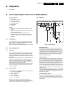
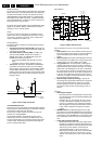
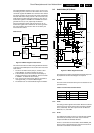
Reset Circuit
Figure 9-10 Block diagram of reset circuit
This reset circuit takes care that booting the different devices
on the mono board takes place in the correct order. The correct
reset order is:
1. The Power On Reset circuit (delay t1) creates a reset
signal 'RESETn' to reset the STi55xx and Furore .
2. In the meantime, the Power On Reset circuit (delay t1)
creates a reset signal 'CLK_STBCTRL', which is inverted
to 'RESETn', to enable the Clock Factory.
3. Then, the Power On Reset circuit (delay t2) generates a
reset signal 'RES_P' to reset the Basic Engine.
4. The STI55xx can now reset the Basic Engine via 'RSTN'.
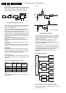
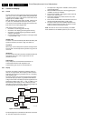
9.4 Audio/Video (A/V) Board
Figure 9-11 Block diagram A/V board
This board is the interface panel between the DVD-player and
its peripherals. See also block diagram in Chapter 6.
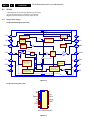
9.4.1 Control
The control of the A/V board is done by the I
2
C-decoder IC7104
(see table below):
Table 9-2 Control lines overview IC7104
9.4.2 Video
The analogue video signals from the Mono Board are buffered
before they are fed to the several output connectors (SCART,
Cinch, and SVHS). The video output from the A/V Board is
RGB/YUV, YC, and CVBS.
9.4.3 Audio
The digital audio signals are fed to a 6-channel DAC CS4362
(item 7200, 48-pin LQFP) for the audio output. This DAC
accepts both DSD and PCM data streams.
There is a control line from the STi55xx, called CENTRE_ON,
which is used to switch between the centre channel and front
channels for both SACD- and DVD modes.
RES_P
CLK_STBCTRL
CL 26532053_018.eps
260402
STi55xx
Power On
Reset
Circuit
Delay 1
Furore 2
Clock Factory
Low Voltage
Detection
4.5V
Low Voltage
Detection
4.5V
Basic Engine
Power On
Reset
Circuit
Delay 2
RSTN
RESETn
Description Pin Hi Lo
CLK_SEL 12 Internal clock External clock
DAC_RESET 10 Normal Reset
CENTER_ON 9 ? ?
CL 26532053_019.eps
010502
7201
7321/23
L
7202
7435
7436/37
7440/41/42
7431/32/33
7220
1400
1421
13001403
A MUTE
S/P DIF
RGB/YUV
C-IN
CENTER ON
DCM data
DSD data
384
*
FS
Control
R
AUDIO
STEREO
AUDIO OUT
Y U V
SVHS
1
2
CVBS
CVBS
L / R
AUDIO L / R
Y/C
P50
RGB
STATUS
VIDEO OUT
SCART
DIGITAL
AUDIO OUT
7325/27
L
7300
R
FRONT
7331
C
7301
PCM_CLK
SW
C / SW
MULTI CHANNEL
AUDIO
OUT
7333/35
5413
7604
L
7302
1410
R
SURROUND
OPTICAL
DIGITAL OUT
COAXIAL
Y-IN
CVBS
P50
CENTER
FROM MONO BOARD
A S
7421/23 74257420/22/24
VIDEO
FILTER
BUFFER
VIDEO
FILTER
BUFFER
7200
DAC
7100/01/03
CLOCK
GEN.
VIDEO
FILTER
BUFFER