


English
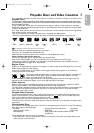
12 Hookups (cont’d)
DIGITAL
AUDIO OUT
COAXIAL
AUDIO
OUT
DVD
L
R
L
R
L
R
S-VIDEO
OUT
COMPONENT
VIDEO OUT
Y
C
B
/
P
B
AUDIO OUT
DVD/VCR
VCR
ANT
-
IN
ANT-OUT
VIDEO OUT
AUDIO IN
VIDEO IN
C
R
/
P
R
L
R
COMPONENT
VIDEO OUT
Y
C
B
/
P
B
AUDIO OUT
DVD/VCR
VIDEO OUT
C
R
/
P
R
L
R
S-VIDEO
OUT
COMPONENT
VIDEO OUT
Y
C
B
/
P
B
AUDIO OUT
DVD/VCR
VIDEO OUT
C
R
/
P
R
AUDIO IN
Y
Cb/Pb
Cr/Pr
COMPONENT
VIDEO IN
L
R
AUDIO IN
S-VIDEO IN
L
R
Back of TV
Back of TV
Audio and
Video IN Jacks
on TV
Antenna or Cable TV
Signal to ANT-IN Jack
Audio Cables
Video Cable
AUDIO IN
VIDEO IN
L
R
1
2
2
2
3
b
3
c
3
a
1
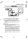
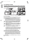
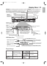
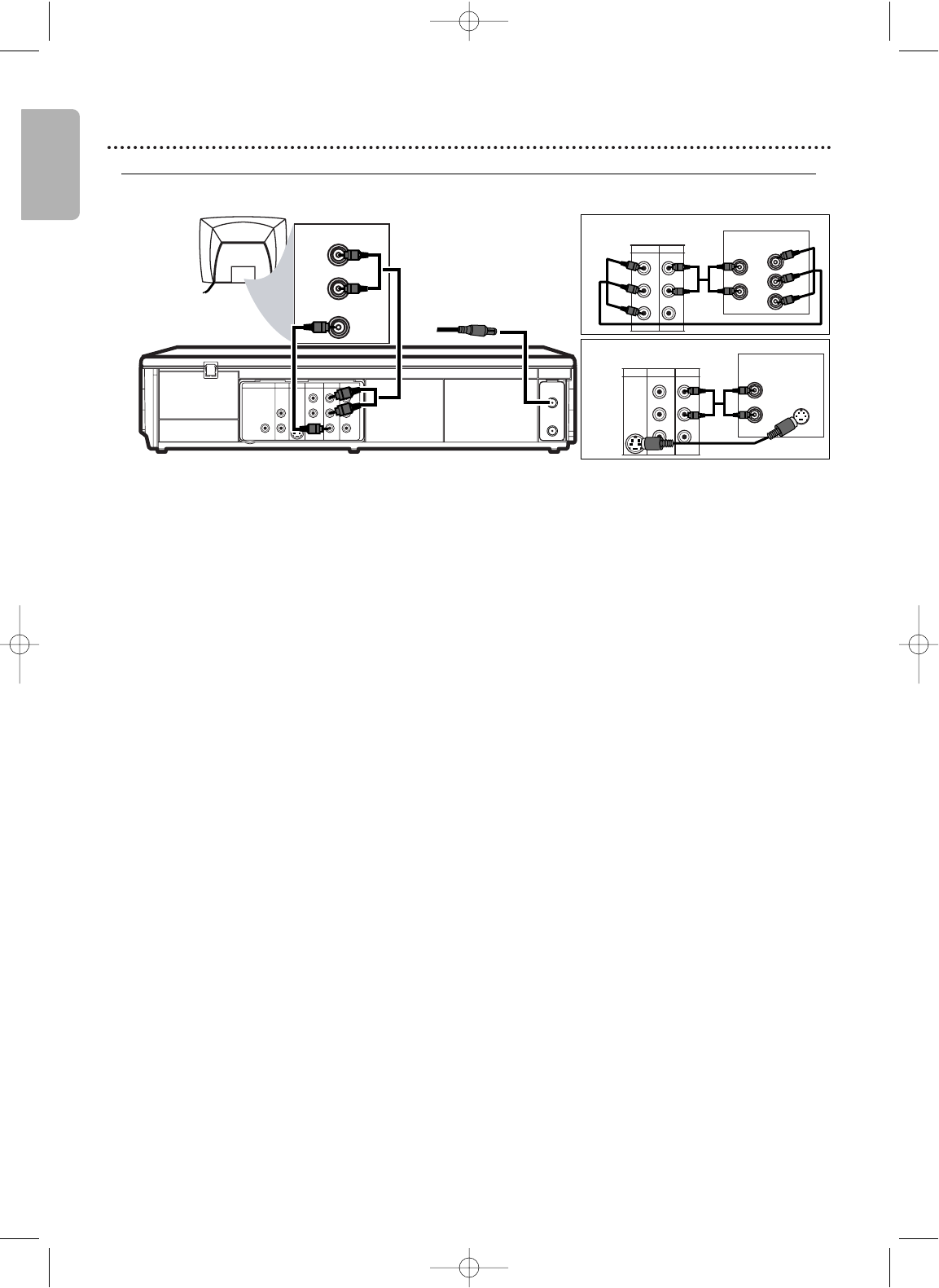
Connect the antenna or Cable TV signal to the ANT-IN (Antenna In)
jack of your DVD/VCR.
2
Connect the red and white audio cables (supplied) to the red and white
DVD/VCR AUDIO OUT jacks on the DVD/VCR and to the red and
white AUDIO IN jacks on the TV. Match the cable colors to the jack colors. If
the TV has a single AUDIO IN jack, use the white audio cable to connect the
DVD/VCR’s white DVD/VCR AUDIO OUT (left) jack to the TV’s AUDIO IN jack.
You will not use the red cable. Or,purchase a “splitter” audio cable to go from the
left/right AUDIO OUT jacks of the DVD/VCR to the TV’s single AUDIO IN jack.
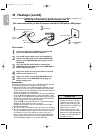
3
a
Connect the yellow video cable (supplied) to the DVD/VCR VIDEO
OUT jack on the DVD/VCR and to the VIDEO IN jack on the TV.The
VIDEO IN jack on the TV is usual
ly yellow and may be labelled CVBS,
Composite or Baseband video.
3
b
Connect component video cable (not supplied) to the COMPONENT
VIDEO OUT jacks on the DVD/VCR and to the COMPONENT
VIDEO IN jacks on the TV. The Co
mponent Video In jacks on the TV are
usually red, blue and green.
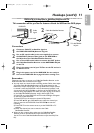
3
c
Connect an S-Video cable (not supplied) to the S-VIDEO OUT jack
on the DVD/VCR and to the S-VIDEO IN jack on the TV.
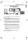
The connections 3b and 3c only supply video (picture) for the DVD player of
the DVD/VCR.Therefore, in order to use the VCR features or view TV channels
at the DVD/VCR, you still need to either connect the RF coaxial cable between
the ANT-OUT jack of the DVD/VCR and the TV’s Antenna In jack,or connect
the yellow video cable.To connect the supplied RF coaxial cable, see step 2 on
page 9.To
connect the supplied yellow video cable, see step 3a.
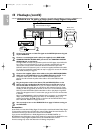
4
Connect the power cords of the TV and the DVD/VCR to a power
outlet.Turn on the TV and set it to the correct Video In channel.
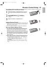
If you are using the RF coaxial cable for VCR playback, choose channel 3 or 4 at
the TV.If you are using the yellow video cable for VCR playback, choose the Video
In channel at your TV. To find the correct Video In channel, go to your lowest TV
channel and change channels downward until you see VCR playback on the TV
screen.To help you find the right Video In channel, turn on the DVD/VCR. Press
DVD to put the DVD/VCR in DVD mode.With no disc in the player,a large DVD
Video logo will appear on the TV screen when you get the TV on the correct
Video In channel.
5
You are ready to turn on the DVD/VCR. Go to page 16 to complete the
first-time setup.
DVD/VCR to a TV that has Audio/ Video, Component Video or S-Video In jacks
H982NUD_EN1 3/2/06 6:56 PM Page 12