


Connecting up
02
16
En
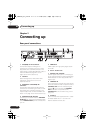
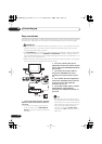
Easy connections
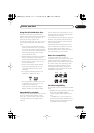
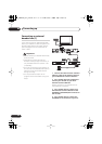
The setup described below is a basic setup that allows you to watch and record TV programs,
and play discs. Other types of connections are explained starting on the following page.
Important
• These connections use SCART cables (not supplied). If your TV (or VCR) does not have a
SCART connection, if you want to use the supplied audio/video cable, see
Using the
supplied audio/video cable
on page 17.
• The
AV1(RGB)-TV
AV connector can output ordinary (composite), S-video or RGB video,
plus stereo analog audio. The
AV2(INPUT 1/DECODER)
connector accepts ordinary, S-
video and RGB video input, as well as stereo analog audio. See
AV1 Out
and
AV2/L1 In
on
page 135 for how to set them up.
• Before making or changing any rear panel connections, make sure that all components
are switched off and unplugged from the wall outlet.
1 Connect the cable from the antenna/
cable TV outlet to the antenna input on
your VCR.
• If you are not connecting a VCR in the
chain, connect it to the
ANTENNA IN
(RF IN)
jack on this recorder and skip the
next step.
2 Use an RF antenna cable (one is
supplied) to connect the antenna output
of your VCR to the ANTENNA IN (RF IN) of
this recorder.
3 Use another RF antenna cable to
connect the ANTENNA OUT of this
recorder to the antenna input on your
TV.
4 Use a SCART cable (not supplied) to
connect the AV1(RGB)-TV AV connector
on this recorder to the SCART AV
connector on your TV.
5 Use another SCART cable to connect
the AV2(INPUT 1/DECODER) AV
connector to a SCART AV connector on
your VCR.
Tip
• This recorder has a ‘through’ function
which allows you to record a TV program
from the built-in TV tuner in this recorder
while watching a video playing on your
VCR (To use this feature when the
recorder is in standby,
Power Save
must be set to
Off
—see
Power Save
on
page 132).
TV
VCR
Antenna/cable TV
wall outlet
AC IN
DIGITAL
OUT
CONTROL
G-LINK
COAXIAL
IN
S-VIDEO
VIDEO
AUDIO
LR
COMPONENT
VIDEO OUT
Y
P
B
PR
ANTENNA
IN
OUT
OUTPUT
AV 1 (RGB) – TV AV 2 (INPUT 1/DECODER)
S-VIDEO
VIDEO
AUDIO
L
R
INPUT3
HDMI OUT
SCART AV
CONNECTOR
SCART AV
CONNECTOR
ANTENNA
IN
ANTENNA
IN (RF IN)
ANTENNA
OUT
ANTENNA
OUT
ANTENNA
IN
1
2
4
5
3
DVR645H_WY_EN.book 16ページ 2006年7月5日 水曜日 午前10時25分