72
En
Appendix
14
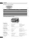
Signal names for 15-pin mini D-sub connecter
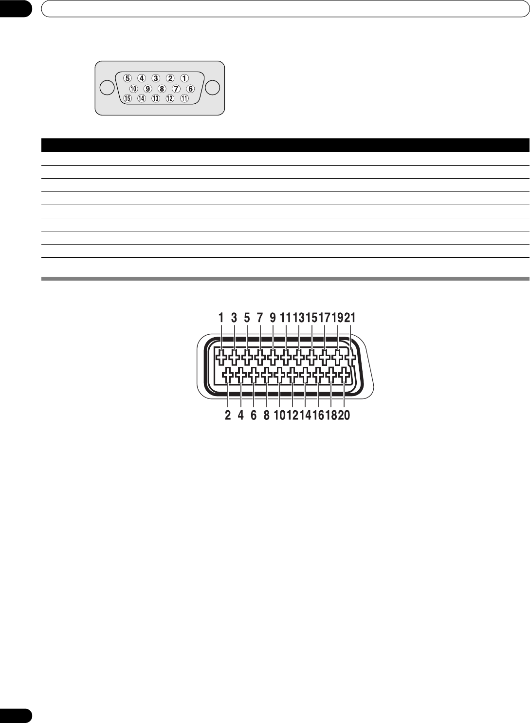
Connecting pin assignments for SCART
Various audio and video devices may be connected via the SCART terminals.
SCART (INPUT 1)
1. Audio right output 8. Audio-video control 15. Red input
2. Audio right input 9. Earth for Green 16. Red/Green/Blue control
3. Audio left output 10. Not used 17. Earth for Video output
4. Common earth for audio 11. Green input 18. Earth for Video input
5. Earth for Blue 12. Not used 19. Video output
6. Audio left input 13. Earth for Red 20. Video input
7. Blue input 14. Earth for Red/Green/Blue control 21. Plug shield
SCART (INPUT 2)
1. Audio right output 8. Audio-video control 15. Chroma S-Video input
2. Audio right input 9. Earth 16. Not used
3. Audio left output 10. AV link control 17. Earth for Video output
4. Common earth for audio 11. Not used 18. Earth for Video input/S-Video input
5. Earth 12. Not used 19. Video output
6. Audio left input 13. Earth 20. Video input/S-Video input
7. Not used 14. Earth 21. Plug shield
SCART (INPUT 3)
1. Audio right output 8. Audio-video control 15. Red input/Chroma S-Video input
2. Audio right input 9. Earth for Green 16. Red/Green/Blue control
3. Audio left output 10. AV link control 17. Earth for Video output
4. Common earth for audio 11. Green input 18. Earth for Video input/S-Video input
5. Earth for Blue 12. Not used 19. Video output
6. Audio left input 13. Earth for Red 20. Video input/S-Video input
7. Blue input 14. Earth for Red/Green/Blue control 21. Plug shield
(Front view)
Pin No. Signal name Pin No. Signal name
1R 9+5V
2 G 10 GND (ground)
3 B 11 Not connected
4 Not connected 12 SDA
5 Not connected 13 HD
6 GND (ground) 14 VD
7 GND (ground) 15 SCL
8 GND (ground)


