


Planar PD520 Owner’s Operating Manual 45
PREL
I
MINA
R
Y
6.1
RS-232 Connection and
Port Configuration
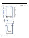
To interface the PD520 with a home theater automation/control system or a PC
running terminal emulation software, connect it to your control system or PC as
shown in
Figure 3-9. (Use a straight-through cable.)
Configure the RS-232 controller or PC serial port as follows: no parity, 8 data bits,
1 stop bit and no flow control. Set the baud rate to match that of the PD520
RS-232 port. To check the baud rate setting, select
Baud Rate from the Installer
menu (refer to page 39).
6.2
Serial Command Syntax
• Commands are in ASCII format and are not case-sensitive.
• A carriage return is not required after a command.
• When you send a valid command, the PD520 executes it and acknowledges
it with a right-bracket character (]) followed by the four-digit numeric code
you sent; for example, ]0002.
• When you send an invalid command (one followed by values outside the
valid range for that command), the PD520 ignores it and returns >MAX or <MIN
instead of the four-digit code.
• When you send an unrecognized/misspelled command, the PD520 ignores it
and returns -N/A instead of the four-digit code.
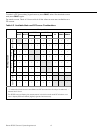
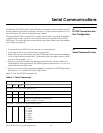
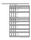
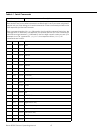
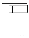
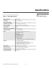
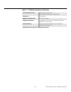
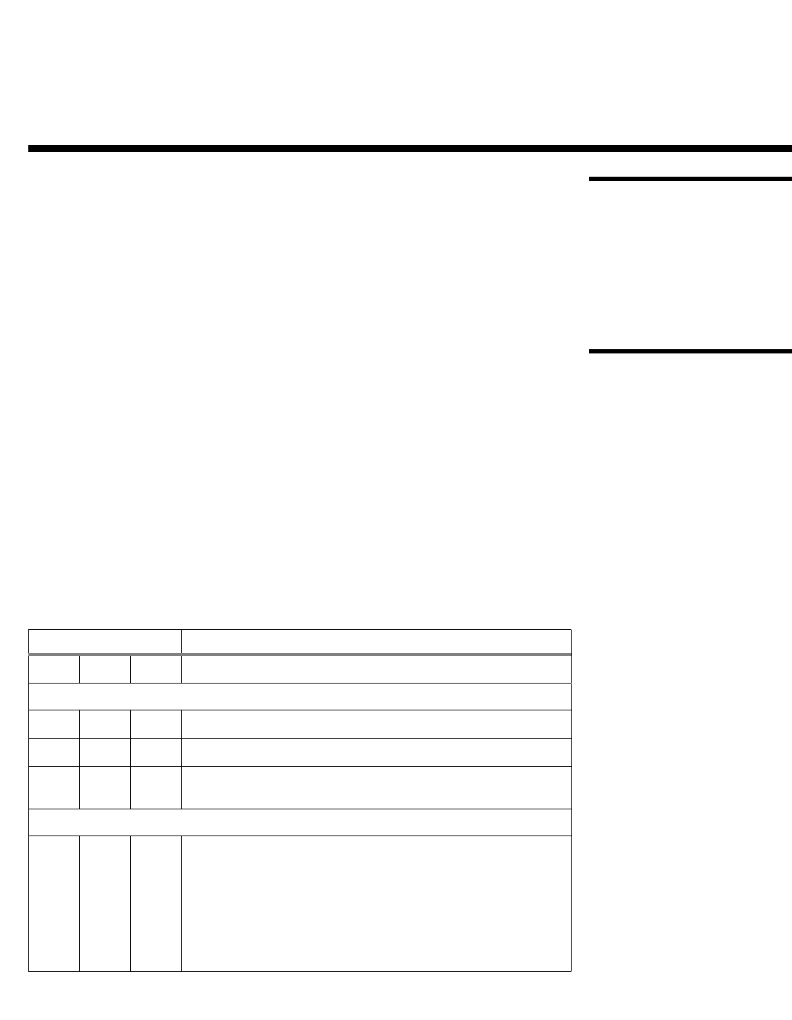
Table 6-1 lists the RS-232 command set.
6. Serial Communications
Table 6-1. Serial Commands
Command Description
[ S3A 0###
Set audio volume to ### ( = 000-100)
Example: [S3A0075 sets volume to 75
[ +3A
Audio volume up
[ -3A
Audio volume down
[ S3E 000#
Audio mute (speakers/headphones)
0 = not muted, 1 = muted
Example: [S3E0001 mutes the audio output
[ S4A 000#
Main input selection
1 = Input1
2 = Input2
3 = Input3
4 = Input4
6 = RGB
8 = HDMI1
9 = HDMI2