


6
7
Chapter 3
IDENTIFYING FRONT PANEL
This section identies all the major components of the front panel. The front panel is
shown, followed by a description of each panel feature. The indicator panel is described
in detail in the next chapter.
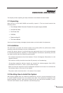
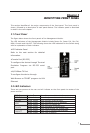
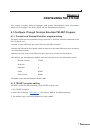
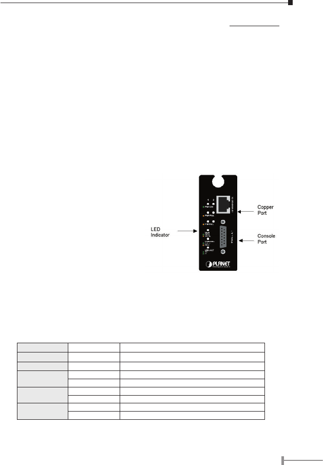
3.1 Front Panel
The gure below shows the front panels of the Management Module.
The LED indicators of the Management Module include Power On, Power Fail, Fan Fail,
MGM, Console and Link/ACT. The following shows the LED indicators for the Switch along
with an explanation of each indicator.
•LED Indicator Panel
Refer to the next section for detailed
information.
•Console Port (RS-232)
To configure the device through Terminal
Emulation Program via RS-232 serial
port.
•10/100Base-TX Port
To configure the device through
Web Browser or TELNET program via LAN
Ethernet.
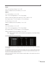
3.2 LED Indicators
There are two powers at the rear and will indicate on the front panel the status of the
power and fan:
PWR On Lights Green when the power is inserted
PWR Fail Lights Amber when the power is inserted and it is fail
Fan Fail Lights Amber when the fan is fail to work
MGM
Blinks Green when the device CPU is working
Lights Amber when the CPU works fail
Console
Blinks Green when the data is transmitting
Blinks Amber when transmitting the wrong data
LNK/ACT
Lights Green when link to networking Ethernet
Blinks Green when link is activity