


@
CAUTION
TO AVOID DAMAGE:
1, DO NOT CONNECT
SPEAKER OUTPUT
TO A SEPARATE
AMPLIFIER OR
TO SPEAKERS
CONNECTED TO
ANOTHER
PRODUCT.
2. DO NOT CONNECT
LEFT AND RIGHT
SPEAKER OUTPUTS
TOGETHER.
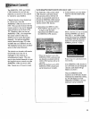
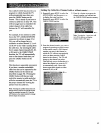
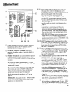
@CABLE/ANTENNA Connectors-used when attaching a
home antenna and/or a cable-TV SYstemtoyour TV.
Connection details are on pages 32-34.
@EXTERNAL SPEAKERS direct
Terminals-permit
connection of auxiliary speakers. Connection details are
on pages 45.
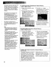
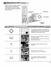
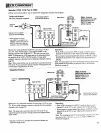
SPEAKER Switch-when you connect additional speakers
tothe EXTERNAL SPEAKERS terminals on the TV, this
switch lets you optimize the sound for the speaker location
you choose.
• If you place the speakers on each side of the TV, put
switch in EXT position. The internal audio from the TV's
speakers will be muted.
• If you place the speal_ers behind the viewer (at the back
of the room), put switch in INT/EXTSURR position.
This maintains normal volume of the TV's internal
speakers and a surround signal to rear speakers.
• Details about connecting speakers to the TV are on
pages 45.
IMPORTANT: Always place switch in INT/EXTSURR
position if no external speakers are used (or if external
speakers are ever disconnected).
@@
@@
@@
@
®
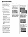
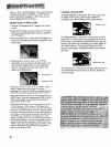
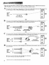
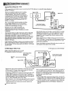
SELECT OUT Jacks-provide fixed-level audio and
video output from whatever is displayed on the TV
screen (except signal from S-VIDEO connector). Provide
audio and video signals suitable for recording.
Can be used for several applications such as:
• VCR editing with two or three VCR's (page 38).
• recording TV programs onto a camcorder (page 41).
• recording cable-TV programs onto a VCR that is not
cable-ready (page 38).
• recording audio onto an audio cassette tape recorder
(page 43).
Notes:
• Remember that the signal coming out of these jacks is
whatever you see (and/or hear) on the TV screen. So,
whatever you want to record mustbe displayed on the TV
screen during recording. Menus, statusdisplays, and special
effects such as picture-in-picture and channel guide will not
appear inthe recording.
• Video signals fromS-VIDEO connector can not be recorded
from the SELECT OUT VIDEOjack. To record froman
S-VHS component connected to the S-VIDEO connector, you
must also connect the video cable to the VIDEOINPUT 1 jack
and then select channel 91 on the TV screen.
INPUT 2 Jacks-provide for direct connection of video
devices (like VCR's) or compatible home computers and
TV games with audio/video outputs. To see the signals
from a device that is connected to the INPUT 2 jacks,
tune your TV to channel 92.
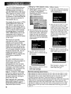
INPUT 1 Jacks-provide for direct connection of video
devices (like VCR's) or compatible home computers and
TV games with video/audio outputs. To see the signals
from a device that is connected to the INPUT 1 jacks,
tune your TV to channel 91.
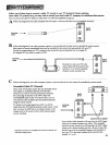
S-VIDEO Connector-provides for direct S-VHS video
connection from S-VHS VCR or camcorder.
Remember to also connect the S-VHS VCR's or
camcorder's audio jack(s) to the TV's INPUT 1 LEFT
and/or R/MONO audio jacks. This is necessary because
S-Video cables only carry the super video (picture), not
the audio signal. Connection details are on pages 38
and 41.
Signals from S-VHS devices connected to the TV's
S-VIDEO connector and INPUT 1 audio jack(s) can be
viewed by pressing the TV button followed by 9 then 0
on the remote control-(or by scanning to TV channel 90
if you have added "90" to channel memory as described
on page 24).
Note: If you want to use the SELECT OUT jacks, remember to
alsoconnect the S-VHS component's regular video cable to the
VIDEO INPUT I jack, and then tune to channel 91.
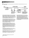
HI FI OUT Jacks-feed volume-controlled stereo audio
out from whatever is displayed on the TV screen. Allow
connection of audio amplifier and let you adjust sound
level with TV's remote. Connection details are on page 43.
31