8 Runco VX-33i Installation/Operation Manual
PRE
L
IMINAR
Y
2.3
VX-33i Rear Connector
Panel
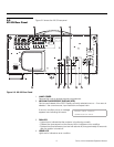
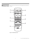
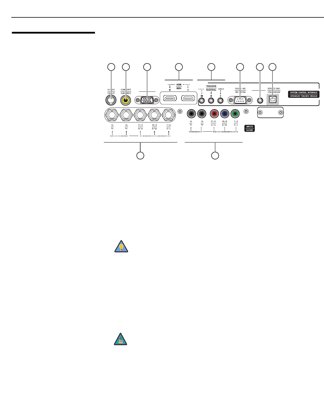
Figure 2-3 shows the rear connector panel on the VX-33i, and the paragraphs that follow
describe them.
Figure 2-3. Rear Connector Panel
1. HD2 INPUT
Five BNCs for connecting either RGB or component high-definition sources (up to
1080p). The VX-33i automatically detects the input signal resolution.
2. HD1 INPUT
Five RCA-type connectors for either RGB or component high-definition sources (up to
1080p). The VX-33i automatically detects the input signal resolution.
3. SERVICE ONLY
For future use.
4. WIRED REMOTE
Wired input from an external remote control or infrared receiver. It is a 3.5-mm, mini
phono jack, wired as follows:
Ring = +5V
Tip = IR Input (TTL level)
Sleeve = Ground
5. RS-232/485 CONTROL PORT
A male, 9-pin D-sub connector for interfacing with a PC or home theater
automation/control system. (Currently, only RS-232 interface is supported.)
6. 12-VOLT (750 mA) TRIGGER OUTPUTS
Connection for up to three (3), 12-volt trigger-controlled devices. These can be
retractable screens, screen masks or the Runco CineWide with AutoScope system.
For best results, do not run your DVD player in progressive mode.
When an external remote control or infrared receiver is connected
to the wired IR input, the IR sensor on the front of the VX-33i is
disabled.
WIRED REMOTE
WIRED REMOTE
HD2 (BNC)
HD1 (RCA)
HD1 (RCA)
HD2 (BNC)
HD3 (VGA / Y-Pb-Pr)
HD3 (VGA / Y-Pb-Pr)
Service port.
Not for user
access
10 9 8 7 6 5 4 3
2
1
Tip
Note


