


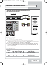
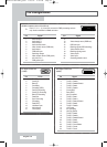
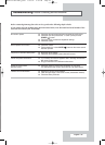

Pin Configurations
➢
Pins 5, 7, 9, 11, 13, 15 and 16 are used for RGB processing and are
only wired on the
Ext.1 or Ext.3 connector.
Pin Signal
1 Audio output R
2 Audio input R
3 Audio output L
4 Audio chassis return
5 Video chassis return (RGB blue)
6 Audio input L
7 RGB blue input
8 Switching voltage
9 Video chassis return (RGB green)
10 AV-Link (Ext 1)
11 RGB green input
Pin Signal
12 -
13 Video chassis return (RGB red)
14 -
15 RGB red input
16 Blanking signal (RGB switching)
17 Video chassis return
18 Blanking signal ground
19 Video output
20 Video input
21 Screening/chassis return
SCART Connector (Ext.1/Ext.2/Ext.3)
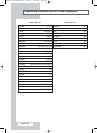
Pin PC IN
1 Red (R)
2 Green (G)
3 Blue (B)
4 Grounding
5 Grounding (DDC)
6 Red (R) Grounding
7 Green (G) Grounding
8 Blue (B) Grounding
9 Reserved
10 Sync Grounding
11 Grounding
12 Data (DDC)
13 Horizontal sync.
14 Vertical sync.
15 Clock (DDC)
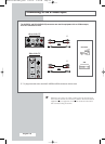
PC Input Connector
(15Pin)
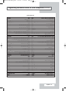
Pin Signal
1 T.M.D.S. Data2-
2 T.M.D.S. Data2+
3 T.M.D.S. Data2/4 Shield
4 T.M.D.S. Data4-
5 T.M.D.S. Data4+
6 Clock (DDC)
7 Data (DDC)
8 Not Connected
9 T.M.D.S. Data1-
10 T.M.D.S. Data1+
11 T.M.D.S. Data1/3 Shield
12 T.M.D.S. Data3-
13 T.M.D.S. Data3+
14 +5V Power
15 5V Grounding
16 Hot Plug Detect
17 T.M.D.S. Data0-
18 T.M.D.S. Data0+
19 T.M.D.S. Data0/5 Shield
20 T.M.D.S. Data5-
21 T.M.D.S. Data5+
22 T.M.D.S. Clock Shield
23 T.M.D.S. Clock+
24 T.M.D.S. Clock-
DVI Input Connector
(24Pin)
English - 64
BN68-00718S-00Eng_0825 8/25/04 2:09 PM Page 64