


Overview
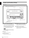
Location and Function of Parts
11
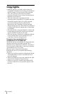
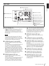
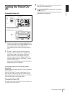
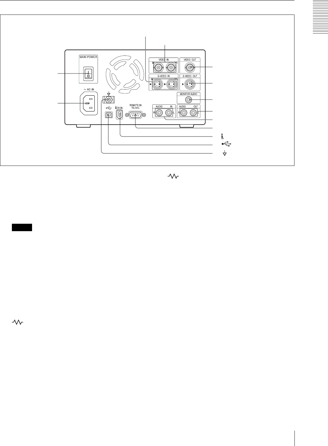
Rear Panel
1 MAIN POWER switch
Switch to the = side to turn the power on. Switch to
the z side to turn the power off. Normally you
should leave this switch in the on position and
power the unit on and off with the power switch on
the front panel.
Note
If you need to turn the main power off when not
using the unit for long periods and so on, always
power the unit off with the 1 (power) switch on the
front panel before setting this switch to off.
2 S-VIDEO IN connectors (4-pin mini DIN)
The left S-VIDEO IN connector inputs analog S
video signals.
The two connectors are loop-through connectors. If
you connect S video input signals to the left
connector, you can bridge-connect the signal to
other equipment via the right connector (marked
). Thus the same signals which are input to the
left connector are output from the right connector to
other equipment. When no connection is made to
the right connector, the left connector is terminated
automatically with an impedance of 75 Ω.
3 VIDEO IN connectors (BNC type)
The left VIDEO IN connector inputs analog
composite video signals.
The two connectors are loop-through connectors. If
you connect composite video signals to the left
connector, you can bridge-connect the signal to
other equipment via the right connector (marked
). Thus the same signals which are input to the
left connector are output from the right connector to
other equipment. When no connection is made to
the right connector, the left connector is terminated
automatically with an impedance of 75 Ω.
4 VIDEO OUT connector (BNC type)
This connector outputs analog composite video
signals.
5 S-VIDEO OUT connector (4-pin mini DIN)
This connector outputs the analog S video signals.
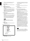
6 MONITOR AUDIO connector (phono jack)
This connector outputs monaural audio signals for
monitoring.
The audio signals to be output from this connector
can be selected among from audio channel 1, audio
channel 2, or mixed audio signals, using AUDIO
MON CH (see page 47) of the SETUP MENU.
7 AUDIO OUT L/R connectors (phono jack)
These connectors output analog audio signals.
8 AUDIO IN L/R connectors (phono jack)
These connectors input analog audio signals.
9 REMOTE IN RS-232C connector (9-pin)
This is a 9-pin RS-232C interface which is
compatible with the SVO-9500MD video cassette
recorder protocol.
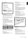
2 S-VIDEO IN connectors
3 VIDEO IN connectors
4 VIDEO OUT connector
5 S-VIDEO OUT connector
6 MONITOR AUDIO connector
7 AUDIO OUT L/R connectors
8 AUDIO IN L/R connectors
qs Equipotential ground terminal
connector
qd -AC IN connector
9 REMOTE IN RS-232C connector
1 MAIN POWER switch
0 DV IN (i.LINK) connector
qa USB connector