


Chapter 2 Location and Function of Parts
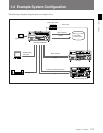
2-4 Chapter 2 Location and Function of Parts
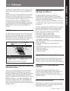
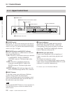
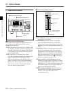
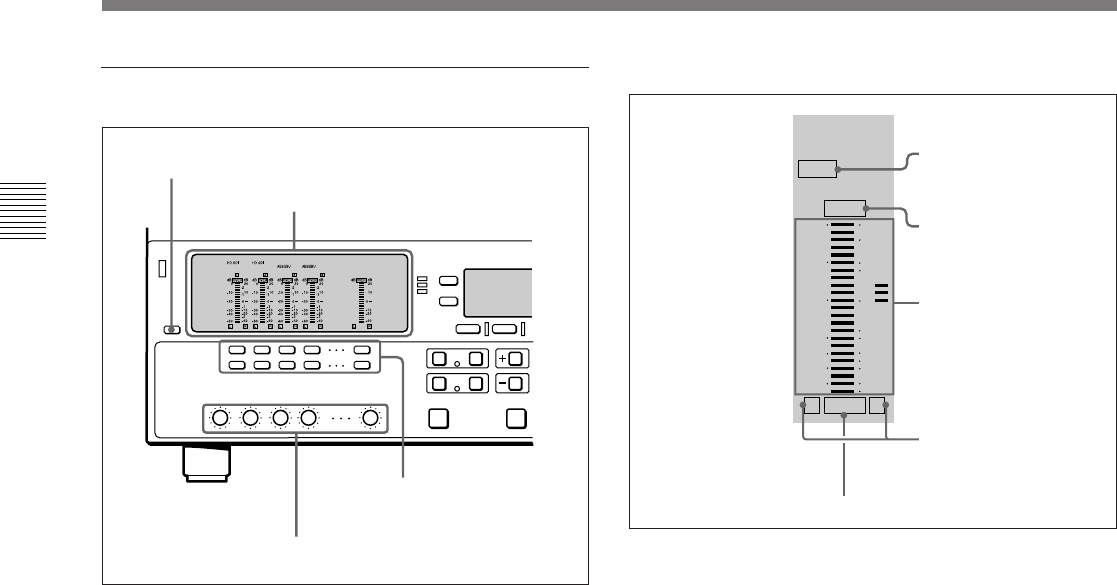
1 Audio control section
1 DISPLAY FULL/FINE button
Pressing this button toggles the display mode of the
level meters in the audio setting display section
between FULL and FINE.
FULL: The display covers the range –60 dB to 0 dB
or –40 dB to +20 dB as selected using setup menu
item 806. In this mode the segment of the display
corresponding to the current audio level and all
lower segments light.
FINE: The display is enlarged, with a step of
0.25 dB. A segment indicating the reference level
lights. In this mode only the segment of the
display corresponding to the current audio level
lights. If the audio level exceeds the maximum
display level, the top segment flashes, and if the
audio level goes below the minimum display
level, the bottom segment flashes.
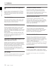
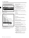
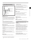
2 Audio setting display section
DATA indicator: Lights when the audio signals are
recognized as data signals.
OVER indicator: While the unit is in playback
mode, this lights when the level of the audio
signal on the corresponding channel exceeds the
maximum level that can be indicated on the level
meter.
Level meter: Displays the audio signal level when
the unit is in playback mode. You can use the
setup menu to switch the display mode between
PEAK.0 (0 dB is maximum level) and REF.0 (0
dB is the reference level). You can also use the
DISPLAY FULL/FINE button 1 to enlarge the
display only near the reference level.
Monitor channel L and R indicators: Indicate
whether or not the signals of the track are output
to the MONITOR OUTPUT L/R connectors and
PHONES jack. ‘L’ lights to indicate output to the
left monitor channel, and ‘R’ lights to indicate
output to the right monitor channel.
EMPH (emphasis) indicator: While the unit is in
playback mode, this lights when the emphasis
setting is on for the audio signal on the
corresponding track.
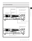
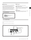
1 DISPLAY FULL/FINE button
2 Audio setting display section
3 Audio monitor
signal selection
buttons
4 PB controls
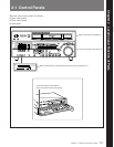
2-1 Control Panels
DATA
OVER
dB dB
EMPH
L R
20
10
2
1
0
0
-10
-20
-30
-40
-60
-1
-10
-20
-40
-2
DATA indicator
OVER indicator
Level meter
Monitor channel L
and R indicators
EMPH indicator