


Chapter 2 Location and Function of Parts
Chapter 2 Location and Function of Parts 2-15
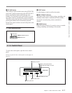
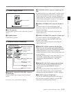
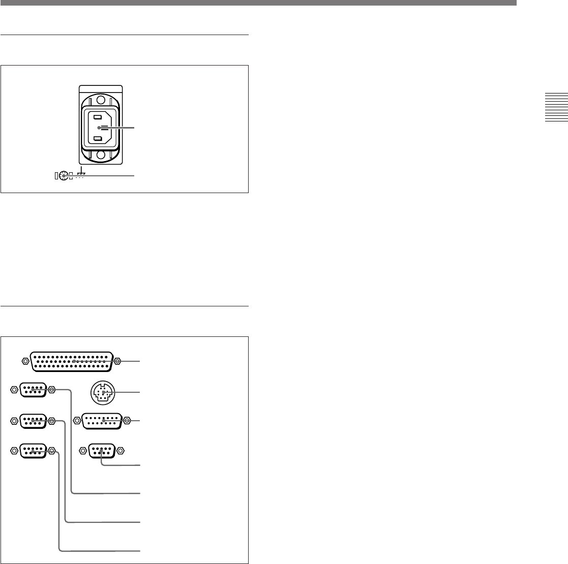
5 Power supply section
1 AC IN connector
Use the optional power cord to connect this to an AC
outlet.
2 Ground terminal
Connect this to ground.
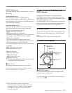
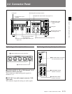
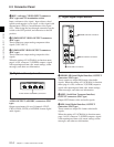
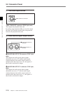
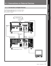
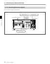
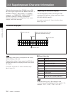
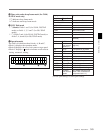
6 External device connectors
1 REMOTE 2 PARALLEL I/O(50P) connector
(D-sub 50-pin)
Connect remote control signals from an external
device.
For details, refer to the Installation Manual.
2 CONTROL PANEL connector (round type, 10-
pin)
In addition to the lower control panel, a similar control
panel can be connected to this unit. To connect such a
second control panel, use this connector. When two
control panels are connected, use the PANEL SELECT
switch on the switch panel (see page 2-11) to specify
which control panel will control this unit.
3 VIDEO CONTROL(15P) connector (D-sub 15-
pin)
For remote control of the internal digital video
processor, connect an optional BVR-50/50P Video
Remote Control Unit.
Always power off this unit before connecting the
remote control unit.
4 VIDEO CONTROL(9P) connector (D-sub 9-pin)
For remote control of the internal digital video
processor, connect an optional HKDV-900 Video
Remote Control Unit.
Always power off this unit before connecting the
remote control unit.
5 REMOTE 1-IN(9P) connector (D-sub 9-pin)
When using this unit together with another HDCAM
VTR, and a BVE-series BVE-700/900/910/2000/9000/
9000P/9100/9100P or other editor, connect the
optional 9-pin remote control cable from the other unit
to this connector.
Depending on the setting of setup menu item 211, you
can use this connector alone, or in a loop-through
configuration with the REMOTE 1-OUT(9P)
connector.
6 REMOTE 1-OUT(9P) connector (D-sub 9-pin)
This provides the loop-through output for remote
control signals from the REMOTE 1-IN(9P)
connector.
Depending on the setting of setup menu item 211, you
can use this connector alone, or in a loop-through
configuration with the REMOTE 1-IN(9P) connector.
7 RS-232C connector (D-sub 9-pin)
Use this for monitoring and diagnosis of the state of
this unit from an external computer, using the ISR
(Interactive Status Reporting) function.
1 AC IN connector
REMOTE 1-IN(9P)
CONTROL PANEL
REMOTE 2 PARALLEL I/O(50P)
VIDEO CONTROL (15P)
REMOTE 1-OUT(9P)
RS232C
VIDEO CONTROL (9P)
1 REMOTE 2 PARALLEL
I/O(50P) connector
2 CONTROL PANEL
connector
3 VIDEO CONTROL(15P)
connector
4 VIDEO CONTROL(9P)
connector
5 REMOTE 1-IN(9P)
connector
6 REMOTE 1-OUT(9P)
connector
7 RS-232C connector
2 Ground terminal