


C-8
SC827 Chassis Manual
BZ1
+
7
J10
7
J12
7
J14
7
J16
7
J22
7
J23
7
J24
7
J25
7
J5
7
J6
7
J7
7
J8
JP49
JP26
TP3
F18
F13
F14
F15
F16
X1
L2
JP18
1 3
JP30
1
3
41
JP60
41
JP59
41
JP58
4
1
JP55
4
1
JP54
4
1
JP57
4
1
JP56
41
JP65
JF4
1
2
19
20
JF3
1
2
19
20
JF2
1
2
19
JF1
12
19
JF5
JF6
11
12
23
33
34
U6
U11
U10
U8
U9
U3
U4
U2
U1
DESIGNED IN USA
JP48
1
4
JP47
1
4
JP46
1
4
JP13
1
4
JP10
1
4
F10
F11
F12
F17
F1
F2
F4
F5
F7F8
F3
F6
F9
C196
C210
C35
C33
C194
C111
C121
C23
C26
C28
C29
C266
C267
C268
C269
C112
C115
C156
C57
C58
C63
C64
C209
C195
C34
C32
C193
C114
C173
C18
C19
C20
C21
+
C199
+
+
+
C119
+
C197
+
C198
+
C201
+ C3
+
C44
+
C45
+
C84
+
C85
C43
C113
C116
C130
C14
C15
C17
C24
C25
C75
C
A
D1
C
A
D11
R196
R199
R202
R222
R226
R144
R145
R40
R11
R110
R297
R94 R82
R81
R80
R79
R78
R77
R76
R75
R153
R152
R104
R113
D72
D68
D65
D64
D63
D62
D61
D60
D59
D58
D57
D56
D55
U13
JP69
U7
1.01REV:
SAS827T
MACH FINISH
30
ANGLE
SPECIFIED DIMENSIONS
UNLESS OTHERWISE
XXX
XX
X
.010
.03
.1
TOLERANCES
DECIMAL
ARE IN INCHES
ShenDESINGER:
DATE: 01/19/2009
PROJECT NAME:
SAN JOSE,CA 95131
DESIGNED BY SUPERMICRO U.S.A.
www.supermicro.com
TEL:408-503-8000 FAX:408-503-8008
SILKSCREEN
PRIMARY-SIDE
S
UPER
R
S
UPER
S
UPER
S
UPER
S
UPER
S
UPER
S
UPER
S
UPER
S
UPER
S
UPER
S
UPER
S
UPER
S
UPER
S
UPER
S
UPER
S
UPER
S
UPER
S
UPER
RRRRRRRRRR
BAR CODE
OPEN:45
C2-3:55
C
C DEFAULT1-2:50
5
10
1
6
P10:GND
P10:GND
HB
OH
JP30:
10
5
6
1
JP49:
JP26:
P2:ACT#D0
P3:ACT#D1
P4:ACT#D2
P1:ACT#C2
P8:ACT#C0
P9:ACT#C1
P3:ACT#A2
P4:ACT#B0
P7:ACT#B2
P6:ACT#B1
P1:ACT#A0
P2:ACT#A1
JF1-CD
JF1-AB
JF1-D
JF1-C
(FAN)
MB-D
#D2
#D1
#D0
FAN4
(PWR)
MB-D
(FAN)
MB-C
(PWR)
MB-C
FAN3
#C2
#C1
#C0
JF1-A
JF1-B
To P/S
#B2
#B1
#B0
FAN2
MB-B
(FAN)
FAN1
(PWR)
MB-B
#A2
#A1
#A0
(FAN)
(PWR)
MB-A MB-A
JP18
2-3:TEST
1-2:BUZZER ENABLE
OPEN:BUZZER DISABLE
BUZZER RESET
REV 1.01
SAS827T
JP30
JP18
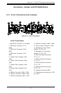
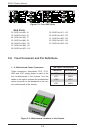
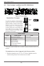
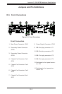
C-7 Front Jumper Locations and Pin Denitions
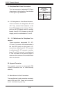
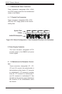
Explanation of Jumpers
To modify the operation of the backplane,
jumpers can be used to choose between
optional settings. Jumpers create shorts
between two pins to change the function
of the connector. Pin 1 is identied with
a square solder pad on the printed circuit
board. Note: On two pin jumpers, "Closed"
means the jumper is on and "Open" means
the jumper is off the pins.
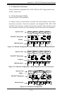
Connector
Pins
Jumper
Setting
3 2 1
3 2 1
Jumper Settings
Jumper Jumper Settings Notes
JP18
Open: Buzzer disabled
1-2: Buzzer enabled (Default)
2-3: Test setting
*Buzzer reset
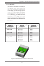
JP30
Overheat Settings
Open: 45º Celsius
1-2: 50º Celcius (Default)
2-3: 55º Celcius
Backplane overheat settings
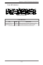
Figure C-8: Front Jumpers
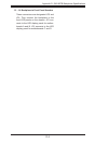
*The buzzer sound indicates that a condition requiring immediate attention has
occurred.
The backplane buzzer alarm is triggered by the following condition:
Backplane temperature over 45º, 50º or 55º Celsius, depending upon the 1.
overheat setting selected. See the table above for details.