


16
TANDBERG Videoconferencing SystemInstallation
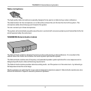
Connecting cables
All cables needed in standard configuration are connected to the codec. Connect these cables to the other parts
of the system:
1. Power cable
Connect the system power cable to an electrical distribution socket.
2. Monitor cables
Connect the 2 BNC (Y/C input at the monitor), the 9 pin DSUB and the power cable to the input on your monitor.
You will find the cables coiled up in the base (for dual monitor systems there will be a coil for each monitor).
3. Microphone cable
Connect the microphone cable to the microphone.
4. Camera cable
Connect the camera and the camera cable.
5a. ISDN cables - using BRI interface
Connect the ISDN cables to the ISDN sockets (S/T-interface) provided by the service provider. Your main number
will be the number associated with the socket to which ISDN cable number 1 is connected.
THE SYSTEM DOES NOT HAVE A BUILT-IN NETWORK TERMINATOR. IF YOUR WALL SOCKET PROVIDES YOU WITH AN ISDN U-INTERFACE, YOU WILL NEED
AN NT1 BETWEEN YOUR SYSTEM AND YOUR ISDN LINE, SEE A PPENDIX 1.
5b. ISDN cable - using the PRI interface
If you are using the PRI interface, the E1/T1 cable should be connected to a CSU (Channel Service Unit). You will
need a CSU between your system and the PRI line from your network provider, see Appendix 3.
5c. Other networks - using the External Network interface
If you are using other networks, please refer to ‘External Network Settings’ and ‘Appendix 2’.
NOTE