HPM-2002-OBEVacuum Gauge Page 22 of 39
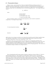
During normal operation the alarm light will illuminate and the TTL output (pin # 2) will go high (+5V) if the
pressure becomes less than the set point.
To view the setpoint using the serial connection, send “L<CR>”.
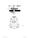
The set points can be adjusted using either the controls on the gauge or the serial connection. To adjust a
setpoint using the manual controls, place the HPM-2002-OBE in either setpoint mode (High or Low). Next, use
the ADJUST rotary encoder until the desired setpoint is displayed. Finally, place the HPM-2002-OBE back in
the Run mode. The new set points are now stored in the HPM-2002-OBE’s memory. Or simply use one of the
Modify High Setpoint Commands e.g. “H={m.dd}E{=+e}<CR>”.
3.3.12. Run Mode
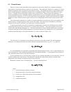
The HPM-2002-OBE will automatically enter the Run mode upon start-up. This is the mode for normal
operation and the mode in which the instrument will spend most of its time. In the Run mode the HPM-2002-
OBE will continuously monitor the pressure; update the alarm conditions, and update the display about ten
times a second.
3.3.13. Cal Mode
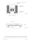
Optimal performance of the HPM-2002-OBE is achieved by performing in situ adjustments to the
calibration coefficients in the Cal mode. There are three calibration coefficients. These are the zero coefficients,
the midrange coefficient, and the atmosphere coefficient. Once a tube has been fully calibrated the midrange
coefficient should never need further adjustment, but it may be helpful to adjust the zero coefficient or the
atmosphere coefficient under certain circumstances. The CAL MODE presupposes that the operator is applying
a known pressure of the correct gas composition (see GAS MODE). The factory calibration points are 800
Torr, 7 Torr, and < 10
-6
Torr. The user’s calibration points are not required to be exactly those values, but
should be somewhat close, and must be within the ranges shown in the figure on page 15. The HPM-2002-
OBE detects the voltage signal within the sensor tube, which is converted and displayed as a pressure reading.
The resulting pressure reading determines which of the three coefficients will be adjusted.


