


HPM-2002-OBEVacuum Gauge Page 26 of 39
4.2. Piezoresistive Sensor
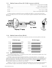
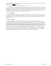
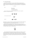
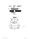
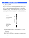
Figure 4.2 shows a typical schematic of a Boron ion implanted Wheatstone bridge network in a Si
diaphragm inverted box type geometry. The inside of the box is evacuated during anodic bonding to a Pyrex
substrate. The membrane has maximum deflection at atmosphere (or higher pressure) and the membrane
resistances change value as the differential pressure is decreased during pump down. The resulting differential
output is
V
o
= SPV+V
1
where
S is the sensitivity
P is the pressure
V is the applied bridge voltage
V
1
is the no load output voltage
Since the sensitivity changes so dramatically with temperature, some correction is required for
compensation. The change in output voltage
To insure temperature invariance,
therefore
which requires for any change in sensitivity to be countered by an equal but opposite change in applied voltage.
The temperature compensation is a network of temperature dependent resistive components and fixed
temperature compensation current source compensation, TCR = -TCS.
Sensitivity of the sensor is proportional to the sensor factor (K), the strain gauge positioning of the
diaphragm (φ) and the diaphragm geometry (θ) thus S ∝ Kφθ. Once the defining geometry of the resistive film
and piezo membrane have been established, the sensor factor is dependent on the crystal orientation of the
membrane material, the doping level and diffusion parameters and the strain gauge geometry. The sensor factor
is essentially the change in resistance for a change in strain or,
L
L
R
R
K
Δ
Δ
=
Boron ion implanted doped Si matrix resistance elements are employed as shown in Figure 4.2. The die is
electrostatically bonded on to a Pyrex substrate in a good vacuum so that the die cavity is evacuated; this
provides maximum deflection at atmospheric pressure. When the sensor is exposed to vacuum the deflection
becomes less and less as the die cavity pressure and the vacuum system pressure equalizes. Eventually the strain
in the membrane due to ∆P becomes zero and only the residual strain in the lattice remains. The bridge resistive
elements are oriented to give maximum change in bridge resistance which in turn gives maximum voltage out for
a given strain.
⎟
⎠
⎞
⎜
⎝
⎛
+=
dT
VdS
dT
SdV
P
dT
dVo
0=
dT
dVo
⎟
⎠
⎞
⎜
⎝
⎛
+−=
dT
dS
SdT
dV
V
11