


19
1-4.
Connections to TV – Video Connection
In the accessory box, you will find two sets of cables: One is the component video cable (with red, green and
blue connectors) and the other is the Audio/Video cable (with yellow, white and red connectors).
For better video quality, it is recommended that you use the HDMI cable, the Mini D-Sub 15-pin cable or the
RGBHV video cable (with 5 RCA connectors). These cables are not included in the HDD-J35 package.
HD MODE Switch selection is essential for several outputs. Refer to the HD MODE Switch table on page 71 for
making the correct switch selection according to your output connection.
You have 6 choices for connecting the video output from the recorder to your TV. Use only one of the following
connections (with (a), (b) or (c) being the best choice):
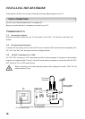
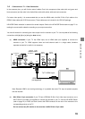
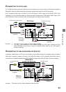
(a) HDMI connection: If your TV has HDMI input, use a HDMI cable (not supplied) to connect the
recorder to your TV. HDMI supports video and multi-channel audio in a single cable, therefore
separate connection for audio is not necessary.
HDMI cable
(not supplied)
To TV HDMI input
HDD-J35
L
R
L
R
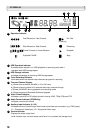
SD VIDEO OUT
RGB
(COAXIAL)
(OPTICAL)
DIGITAL
AUDIO OUT
S-VIDEO
Y/G
P
B
/B
P
R
/R
H
V
VIDEO
HDMI
HD VIDEO OUT
ANALOG
AUDIO OUT
Note: Because HDMI is an evolving technology, it is possible that some TVs may not operate properly
with the recorder.
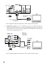
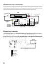
(b) Mini D-Sub 15-pin connection: If your TV has a RGB Mini D-Sub 15-pin video input connector, use a
Mini D-Sub 15-pin cable (not supplied) to connect the recorder to your TV. Set the HD MODE Switch
(refer to page 12) to RGB, and then connect the RGB connector on the rear of the recorder to the
corresponding socket on the TV.
Do not connect any PC monitor to the recorder via Mini D-Sub 15-pin cable.
STARTUP GUIDANCE