


21
(d) YP
B
P
R
connection
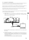
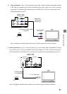
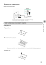
: If your TV has component video inputs, use the component video cable included
in the HDD-J35 accessory box. Set the HD MODE Switch (refer to page 12) to YP
B
P
R
, and then
connect the Y/G, P
B
/B and P
R
/R connectors from “HD VIDEO OUT” on the rear of the recorder to the
corresponding jacks on the TV.
Component video cable
(supplied)
To TV Y/P
B
/P
R
video inputs
HDD-J35
Match the
colors when
connecting
Y
P
B
P
R
Y
P
B
RGB
Y/G
P
B
/B
P
R
/R
H
V
HDMI
HD VIDEO OUT
P
R
RGB
YP
B
P
R
HD MODE
Note: This diagram illustrates video connections only. Refer to Page 22 for Audio connection.
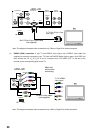
(e)
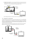
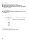
S-Video connection
: If your TV has an S-Video input, use an S-Video cable (not supplied) to connect
the recorder to your TV. Set the HD MODE Switch (refer to page 12) to YP
B
P
R
, and then connect the S-
Video connector from “SD VIDEO OUT” on the rear of the recorder to the corresponding jack on the TV.
S-Video cable
(not supplied)
To TV S-Video input
HDD-J35
SD VIDEO OUT
S-VIDEO
Y/G
P
B
/B
P
R
/R
H
V
VIDEO
HDMI
HD VIDEO OUT
RGB
RGB
YP
B
P
R
HD MODE
Note: This diagram illustrates video connections only. Refer to Page 22 for Audio connection.
STARTUP GUIDANCE