


23
2 CONNECTING TO DVD PLAYER
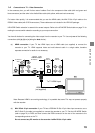
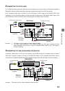
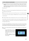
For TV sets with limited component video inputs, this recorder can be used to connect a DVD player through the
Component Video and Stereo Audio input connectors located at the back of the HDD-J35 recorder.
Use a component video cable to connect from the DVD player’s YP
B
P
R
output to the HDD-J35 YP
B
P
R
input
connectors; Use an Audio/Video cable to connect the audio connectors from DVD player’s audio output to the
HDD-J35 Audio L/R input connectors: red to red (right audio) and white to white (left audio).
Component video cable
(supplied)
Audio/Video cable
(supplied)
DVD Player
To DVD audio outputs
To DVD Y/P
B
/P
R
video outputs
HDD-J35
Y
P
B
P
R
Y
P
B
P
R
white
red
Match the
colors when
connecting
RGB
SD VIDEO OUT
S-VIDEO
L1 IN
Y
P
B
P
R
VIDEO
L
R
L
R
Y/G
P
B
/B
P
R
/R
H
V
VIDEO
HDMI
L2 IN
HD VIDEO OUT
576i ONLY
white
red
Important: 1. This setup is only for output connection made via HDMI.
2. The YP
B
P
R
input connectors on this recorder accepts only 576i signal, therefore the DVD
player connected must be set to output in interlaced format. Refer to your DVD player’s
manual for settings.
3
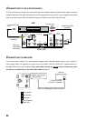
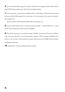
CONNECTING TO CABLE BOX/SATELLITE BOX/VCR
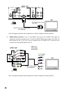
A cable box, satellite box or VCR can be connected to this recorder through the Composite Video and Stereo
Audio input connectors located at the back of the HDD-J35 recorder. Use a composite Audio/Video cable to
connect from the Cable Box/Satellite Box/VCR’s Video/L/R output to the HDD-J35 Video/L/R input connectors.
Audio/Video cable
(supplied)
CABLE BOX/
SATELLITE BOX/VCR
To Audio outputs
To Composite Video
outputs
HDD-J35
white
red
Match the
colors when
connecting
RGB
SD VIDEO OUT
S-VIDEO
L1 IN
Y
P
B
P
R
VIDEO
L
R
L
R
Y/G
P
B
/B
P
R
/R
H
V
VIDEO
HDMI
L2 IN
HD VIDEO OUT
576i ONLY
white
red
Audio/Video cable
(supplied)
Important: This setup is only for output connection made via HDMI.
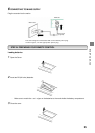
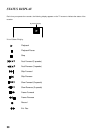
STARTUP GUIDANCE