


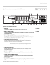


Controls and Functions
6 Vision Model 140/150 Installation/Operation Manual
PRE
L
IMINAR
Y
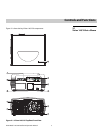
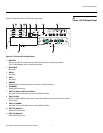
1. TOP IR SENSOR
2. BUILT-IN KEYPAD
The built-in keypad is located at the back of the projector, beside the input panel. Use it
similarly to the TheaterMaster Remote Control to perform service-related tasks on the
projector.
3. INPUT PANEL
Connect the VHD Controller outputs here.
4. LED STATUS DISPLAY
Indicates current operating status of the projector.
5. LAMP COVER
Remove this cover to access the lamp compartment.
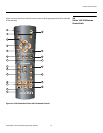
6. REAR FOOT (Stationary)
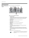
7. POWER INPUT (200 to 240 VAC)
Connect the Vision 140/150 to power here. (The Vision 140 requires 100 to 240 VAC; the
Vision
150 requires 200 to 240 VAC.)
8. FRONT IR SENSOR
9. PROJECTION LENS
10. INTAKE VENT
Allows cool air to enter the projector, to help maintain proper operating temperature.
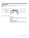
11. ADJUSTABLE FEET (2)
Located on the underside of the projector are two adjustable feet. Raise or lower these
feet when positioning the projector to ensure it is level on all sides so the displayed
image will appear rectangular without any keystone.