


Installation
30 Vision Model 140/150 Installation/Operation Manual
PRE
L
IMINAR
Y
3.7
Connections to the Vision
140/150 and VHD
Controller
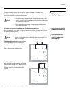
Proceed as follows to connect the VHD Controller to the Vision 140/150, your video sources,
external controller(s) – if present – and AC power.
When connecting your equipment:
• Turn off all equipment before making any connections.
• Use the correct signal cables for each source.
• Ensure that the cables are securely connected. Tighten the thumbscrews on connectors
that have them.
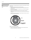
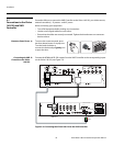
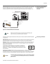
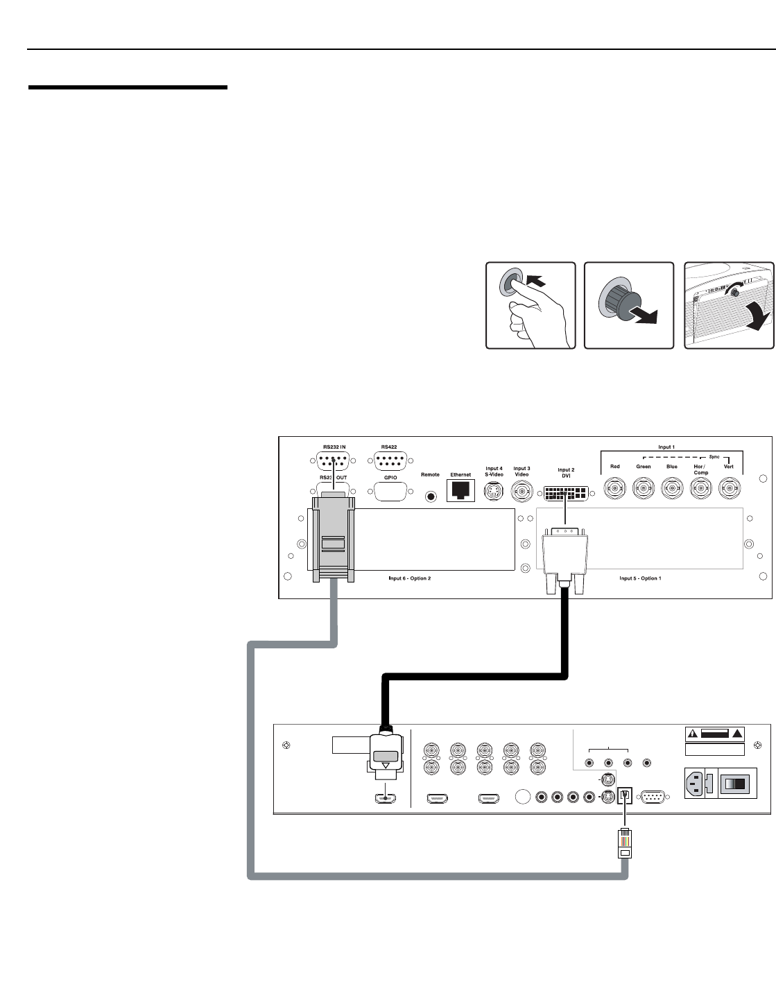
Connector Panel Access To access the connector panel, press
the door release button so it pops out.
Turn the knob clockwise or
counter-clockwise and pull gently on it
to open the door.
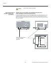
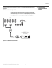
Connecting the VHD
Controller to the Vision
140/150
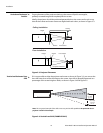
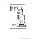
Connect the HDMI and RS-232 outputs from the VHD Controller to the corresponding inputs
on the Vision 140/150; see
Figure 3-9.
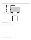
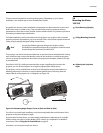
Figure 3-9. Connecting the Vision 140/150 to the VHD Controller
➤
➤
Pb Pr Y
Video
3
IR
RS-232 Control
S-Video 1
S-Video 2
HD1
HD2
1
2
R/Pr G/Y B/Pb
R/Pr G/Y B/Pb H V
HDMI 1 HDMI 2HDMI Out
HV
TRIGGERS
RS-232 Out
CAUTION:
TO REDUCE THE RISK OF ELECTRIC
SHOCK, DO NOT REMOVE COVER. NO USER-
SERVICEABLE PARTS INSIDE. REFER SERVICING
TO QUALIFIED SERVICE CENTER.
AVIS: RISQUE DE CHOC ELECTRIQUE-NE PAS OUVRIR
CAUTION
RISK OF ELECTRIC SHOCK
DO NOT OPEN
!
WARNING:
TO REDUCE THE RISK OF FIRE
OR ELECTRIC SHOCK, DO NOT EXPOSE
THIS APPLIANCE TO RAIN OR MOISTURE.
100-230VAC 50-60 Hz, 165 Watts Max
INPUTS
SYSTEM CONTROL INTERFACE
Component Video
SDI
Option
Serial No
Video Processor / Controller
Model
Made In USA
HDMI OUT
RS-232
OUT