


10
IN
RM OUT-B
OUTIN GG
-
--
++
+
GGGG
GGGG4321
NC
PRIORITY RM IN-BCAMERA
TIME SYNCCONTROL OUT
A
B
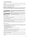
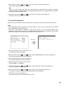
Terminal name
Name
PRIORITY IN
PRIORITY G
NC
CAMERA
+
CAMERA G
CAMERA
-
RM IN-B
+
RM IN-B G
RM IN-B
-
RM OUT-B
+
RM OUT-B G
RM OUT-B
-
Priority Recording Input
Priority Recording Ground
Not connected
Camera Control (RS-485) +
Camera Control (RS-485) Ground
Camera Control (RS-485)
-
Remote Control Input B + (RS-485)
Remote Control Input B Ground
Remote Control Input B
-
(RS-485)
Remote Control Output B + (RS-485)
Remote Control Output B Ground
Remote Control Output B
-
(RS-485)
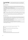
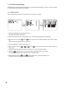
Terminal name
Name
CONTROL OUT 1
CONTROL OUT G
CONTROL OUT 2
CONTROL OUT G
CONTROL OUT 3
CONTROL OUT G
CONTROL OUT 4
CONTROL OUT G
TIME SYNC IN
TIME SYNC G
TIME SYNC OUT
TIME SYNC G
Control Output 1
Control Output Ground
Control Output 2
Control Output Ground
Control Output 3
Control Output Ground
Control Output 4
Control Output Ground
Date/Time Adjustment Input
Date/Time Adjustment Input Ground
Date/Time Adjustment Output
Date/Time Adjustment Output Ground
A
B
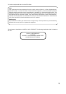
Master
Input Output
Slave 1
Input Output
Slave 2
Input Output
Slave 7
Input Output
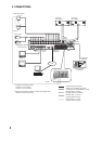
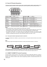
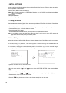
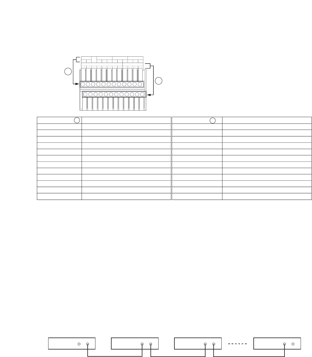
4.2. Control I/O Terminal Connections
The control input and output terminals include: priority recording terminal, camera control terminal, remote
controller input/output terminals, control output terminal, and time synchronization input/output terminals.
Notes
• Ensure that the cable is securely locked into the terminal after connection.
• Use the CPEV-S cable (twisted pair shielded cable) with diameter larger than 0.65 mm for the Control
Input/Output terminal connections. Also be sure to connect the shielded cable to the GND terminal.
• The maximum cable length of the control cable from the Digital Video Recorder to the camera of which
termination is set to ON is 1.2 km. Also the maximum cable length of the control cable from the Remote
Controller to the Digital Video Recorder of which termination switch is set to ON is 1.2 km.
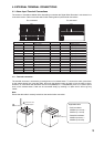
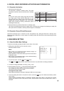
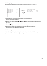
4.2.1. Time synchronization input/output terminal connections
Two different methods are available to synchronize the time, one using both master and slave units, the other
using NTP.
Note
When using a single-channel Digital Video Recorder, set the synchronization interval to "5 seconds."
To synchronize the times of slave units with the time of the master unit, connect the slave units to the master
unit in a series via their input and output terminals. In other words, connect the input of slave number one to
the master unit's output and the input of slave number two to slave number one's output, and so on.
4.3. 10BASE-T/100BASE-TX Terminal Connections
Use this terminal to remotely monitor or control cameras connected to the Digital Video Recorder, or search or
play back their recorded images on a PC web browser. When connecting a PC directly to the Digital Video
Recorder, use a network crossover cable. Use the straight-through cable for connection between them via a
switching hub.