


9
GGGGGGGG
GGGGGGGG
16
8
15
7
14
6
13
5
12
4
11
3
10
2
9
1
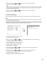
ALARM IN
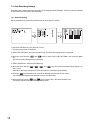
Press down the
Release button.
Insert a cable.
Push the
release button up.
2
1
3
G
GGGGGGGG8765432
9
1
ALARM IN
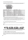
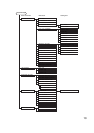
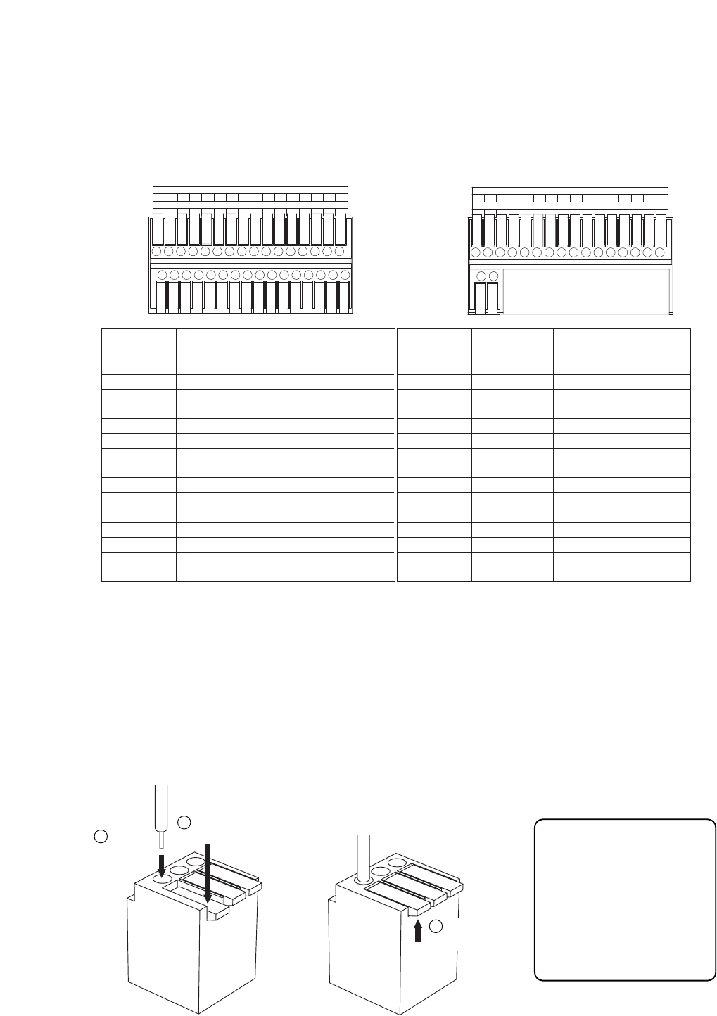
For 16 channel For 9 channel
Applicable cable
• Solid conductor
AWG26 (ø 0.4 mm)
-
AWG16 (ø 1.2 mm)
• Stranded conductor
AWG24 (0.2 mm
2
)
-
AWG20 (0.75 mm
2
)
Terminal name
1
G
2
G
3
G
4
G
5
G
6
G
7
G
8
G
Symbol
Name
ALARM 1
GND
ALARM 2
GND
ALARM 3
GND
ALARM 4
GND
ALARM 5
GNA
ALARM 6
GND
ALARM 7
GND
ALARM 8
GND
Alarm input 1
Signal ground
Alarm input 2
Signal ground
Alarm input 3
Signal ground
Alarm input 4
Signal ground
Alarm input 5
Signal ground
Alarm input 6
Signal ground
Alarm input 7
Signal ground
Alarm input 8
Signal ground
Terminal name
9
G
10
G
11
G
12
G
13
G
14
G
15
G
16
G
Symbol
Name
ALARM 9
GND
ALARM 10
GND
ALARM 11
GND
ALARM 12
GND
ALARM 13
GNA
ALARM 14
GND
ALARM 15
GND
ALARM 16
GND
Alarm input 9
Signal ground
Alarm input 10
Signal ground
Alarm input 11
Signal ground
Alarm input 12
Signal ground
Alarm input 13
Signal ground
Alarm input 14
Signal ground
Alarm input 15
Signal ground
Alarm input 16
Signal ground
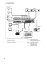
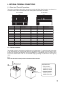
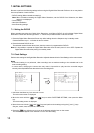
4.1.1. Terminal connection
The terminal connector is unlocked by pressing down on its release button. To connect the cable, press down
on the release button first, insert the cable, then push the release button up again to lock the cable in place.
However, for solid cables with diameters from 0.8 mm(AWG20) to 1.2 mm(AWG16), there is no need to press
down on the release button. Cable can be connected simply by inserting it in place until it will not go any
further.
Note
Ensure that the cable is securely locked into the terminal after connection.
4. EXTERNAL TERMINAL CONNECTIONS
4.1. Alarm Input Terminal Connections
The number of terminals available differs depending on whether the Digital Video Recorder is a 9-channel or a
16-channel version. Refer to the table below when making alarm input terminal connections.