


Page 21
Page 21 of 72 UTY4422-002
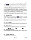
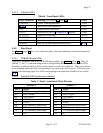
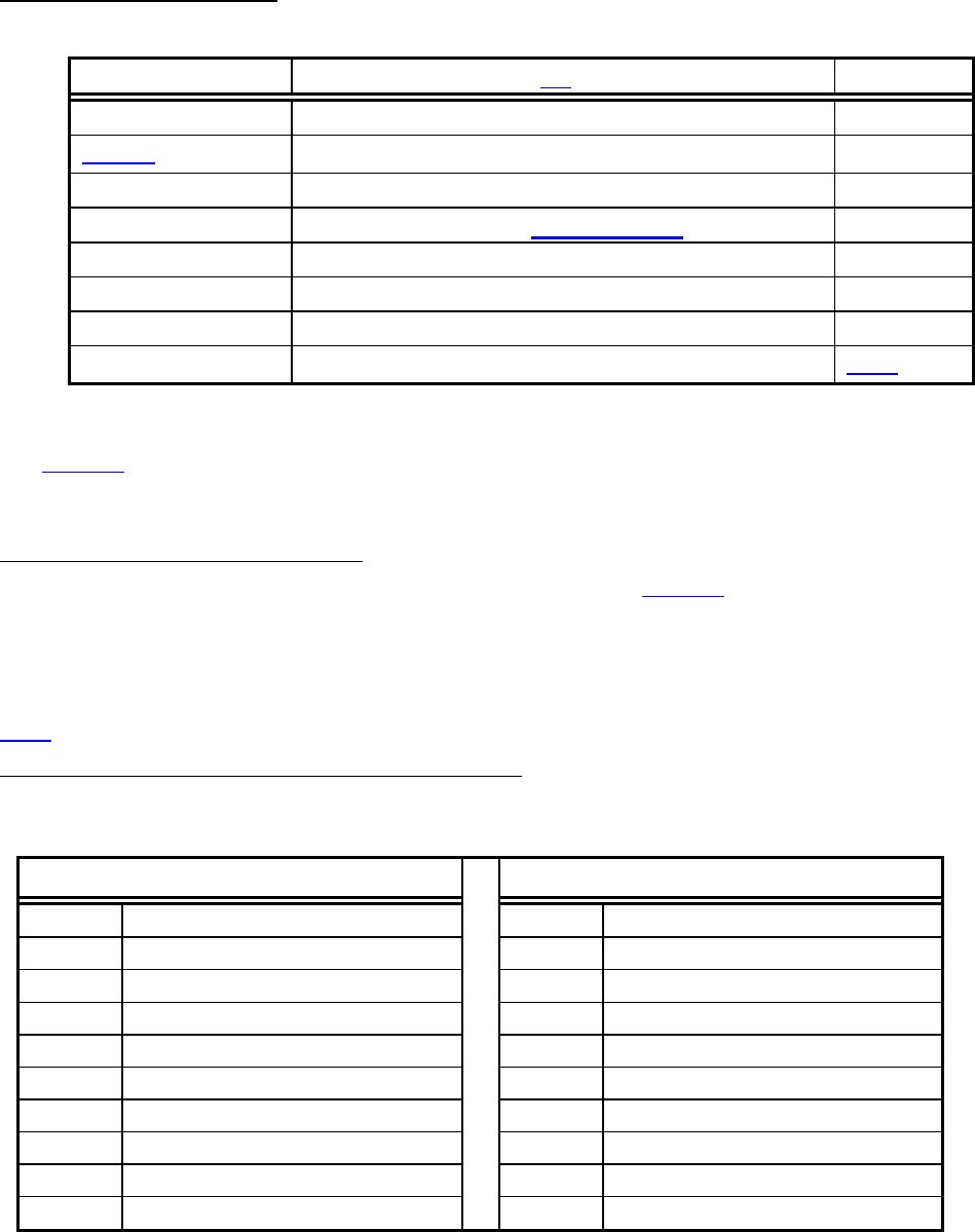
2.4.1.3 Indicator LED’s
Table 6. Front Panel LED’s
Label Mnemonic Meaning [See Section 3.2 (Page 30)] Color
CARRIER Carrier Tracking indication Green
MPEG
Main MPEG mux indication Green
CUE Contact-closure activation Green
AUTH
Authorized to receive COMPEL-CA program
Green
RF LEVEL Signal Level Warning Green
COMPEL™ Network control indication Green
WARNING General warning indication Yellow
ALARM Link lost or other major alarm indication
RED
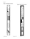
2.4.2 Rear Panel
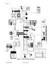
See Figure 4 (Page 26) for a view of the rear panel, where the following controls and connectors
are located.
2.4.2.1 DVB/ASI Module LEDs
There are 2 Indicator LEDs on the DVB/ASI Input module. See Figure 4 (Page 26). They are
labeled “1” and “2” with each being beside a corresponding BNC input connector. The LEDs
illuminate to indicate which is locked to the signal or which was locked last. If the unit is locked
to an incoming signal, the LED corresponding to the input in use will be green. If the unit is not
locked to an incoming signal, The LED corresponding to the input that should be in use will be
RED.
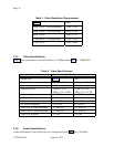
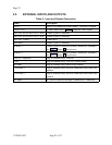
2.4.2.2 Standard DVB Synchronous Interface
Table 7. Serial 1 and Serial 2 Port Pin-outs
SERIAL 1
SERIAL 2
Pin # Signal Pin # Signal
B1 DCD (Internally pulled high) A1 DCD (Internally pulled high)
B2 RXD (Output A2 RXD (Output)
B3 TXD (Input) A3 TXD (Input)
B4 DTR (Not connected) A4 DTR (Not connected)
B5 GNDS A5 GNDS
B6 DSA (Internally pulled high) A6 DSA (Internally pulled high)
B7 RTS (Not connected) A7 RTS (Not connected)
B8 CTS (Internally pulled high) A8 CTS (Internally pulled high)
B9 A9 RI