


Page 69
Page 69 of 72 UTY4422-002
7.3 Modem baud/Password B=( 9600 ,
19.2k
), P-word = ___ ___ ___ ___ ___ ___ (
PASSWD
)
7.4 Local Terminal/front-panel Control: (
Enabled
/ Disabled )
7.5 Printer baud/parity: Baud =( 9600 ,
19.2 k
) ; Parity =( odd , even ,
none
)
7.6 Aux. Data PID [hex]: ( _________________,
1ffe
)
7.7 Aux. Data Baud/Parity: B=( 1200, 2400, 4800,
9600
, 19.2k, 38.4k ); P=( odd , even ,
none
)
8.0 Misc. Audio/Video Setup Parameters
8.1 PCR mode ( auto-adjust to data-rate ,
static
!
) -- “Auto-adjust” required with DVT2000
8.2 PCR offset [hex]: ( _____________ ,
-3000
!
) -- Applicable if “static” above is selected
8.3 Video Pedestal Setup: ( Disabled,
Enabled
!
) -- “Enabled” matches DVT2000
8.4 Video Aspect Ratio: (
Auto Detect !
, 16:9, 4:3 )
8.5 Audio delay [hex]: ( _____________ ,
0
!
) – Sets A/V sync, default value is hex for ‘0’ decimal
8.6 Horiz Delay: NTSC ( __________ ,
34 !
) ; PAL ( ____________ ,
3e !
)
8.7 Optional outputs home-screen alarm/warning bitmask on failure:
Sync Data: (
None
, Warning , Alarm ); ASI Transport: (
None
, Warning , Alarm )
Serial Digital Video [D1]: (
None
, Warning , Alarm )
9.0 Network Settings
9.1 COMPEL PID [hex]: ( _________ ,
1026
!
) -- Next alternate is usually 1030
9.2 Wegener C/A PID [hex, if applicable]: ( _________ ,
1028
!
) -- Next alternate is usually 1032
9.3 Netcon Lock: ( Locked ,
Unlocked
)
9.4 Shared Mode ( Shared ,
Protected
)
9.5 COMPEL Required ( Required ,
Not required
)
9.6 Tag Bypass: (
No
!
, Yes )
--
“Yes” is also known as “ISOG-enabled”
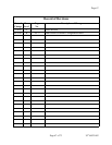
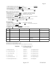
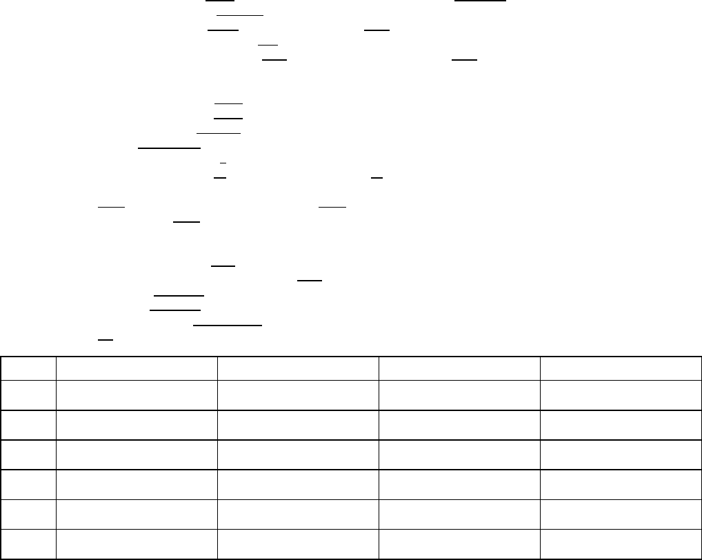
9.7 Timeouts
:
# Description Allowed Range Default Change from Default
1 Fade 0 - 30 seconds
15 seconds !
2 Install 0 - 4660 hours
4660 hours !
3 Carrier Search 0 - 4660 hours
48 hours !
4 No COMPEL 0 - 4660 hours
2 hours !
5 COMPEL Seek 0 – 4660 hours
5 minutes !
6 Header Search 0 – 4660 hours
48 hours !
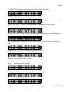
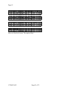
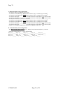
10.0 Information on Option Module Location:
The following are the optional Modules cards that can be added to the UTY4422 unit.
Maximum Qty.
Preferred Module Location inside unit
each per unit (
*
For signal option card)
(
**
Only location available)
A. Balanced Audio Card 2 Module #1
*
See configuration below
B. 14 Function Relay Card 1 Module #1
*
See configuration below
C. 2 Port ASI Input Card 1 Module #1
**
See configuration below
D. ASI Output Card 1 Module #1
*
See configuration below
E. Sync Data Output Card 2 Module #1
*
See configuration below
F. 4 Port RF Input Switch Card 1 Module #2
**
Not configurable