


Page 27
Page 27 of 72 UTY4422-002
2.6 EXPANSION CARD CONFIGURATION
The purpose of this section is to detail the jumper settings and labeling instructions for the Unity
Expansion Cards.
2.6.1 Balanced Audio Expansion Card
2.6.1.1 Audio Card Jumper Configuration
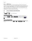
Jumper settings – Dotted and Non-dotted. The headers used here have 3 pins, so a jumper
connecting 2 of these pins can connect pins 1 & 2 or pins 2 & 3. The “Normal” position of this
jumper is marked by a dot on the silkscreen near either pin 1 or pin 3.
Dotted Position - Jumpering pin 2, the center pin, to the pin nearest the dot.
Non-Dotted Position - Jumpering pin 2 to the pin furthest from the dot.
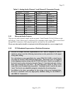
Installing an audio expansion card enables audio channels 3 and 4. You should set jumpers J2,
J3, J4, J6, J7, and J8 on this Audio Card to the “dotted” position.
Only one audio expansion card can be installed in this unit, and must be installed in the “Module
2” position.
2.6.1.2 Audio Card Label Instructions
When a balanced audio expansion card is installed, channels 3 and 4 are used. Set the jumpers
on that card to the “dotted” position, and label the Audio Card Bracket as [CH4 CH3]. As
these cards may be used in several applications, and the channel designations may be different
on each, the outputs must be labeled for each application. To label it:
1. Peel the [CH4 CH3] label from the backing.
2. Press the label onto the rear of the Audio Card Bracket, within the blank rectangle
provided, or cover existing silkscreen text.
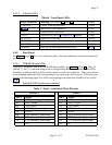
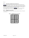
2.6.2 Sync or ASI Output Data Card Jumper Configuration
When you install one SYNC or ASI expansion card, set jumper J9 on that card to the “dotted”
position. See Section 2.6.1 (above) for details on “Dotted” and “Non-dotted” jumper positions.