


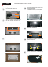
S4
S6
S5
S3
S2
S1
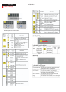
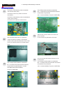
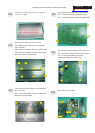
Use a Phillips-head screwdriver screwed the
No.1~4 screws till that interface board and bracket
chassis base firmly attached.
(No1~4 screw size=M3x6; Torque=9~10KGFxCM).
Use a Phillips-head screwdriver screwed the
No.1~5 screws till that power board and bracket
chassis base firmly attached.(No1~4 screw
size=M3x6; No5 screw size=M4x8;
Torque=9~10KGFxCM).
Take a bracket chassis base on a protective
cushion and stick an insulator on the specific
position, take a power board and turn it over. Then,
put it on the specific positions of bracket chassis
base.
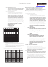
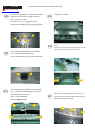
Connect the cable between power board(P802)
and interface board (P301)
Connect the function key cable into interface
board(P303)
Connect the cable between power board(P803)and
inverter board (Cn001)
Connect the FFC cable into interface board
1
2
3
4
4.1 Assembly procedures:
4. Assembly and Disassembly Procedures
1
2
3
4
5
P301
CN01
P803
P802
P303
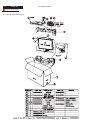
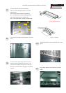
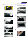
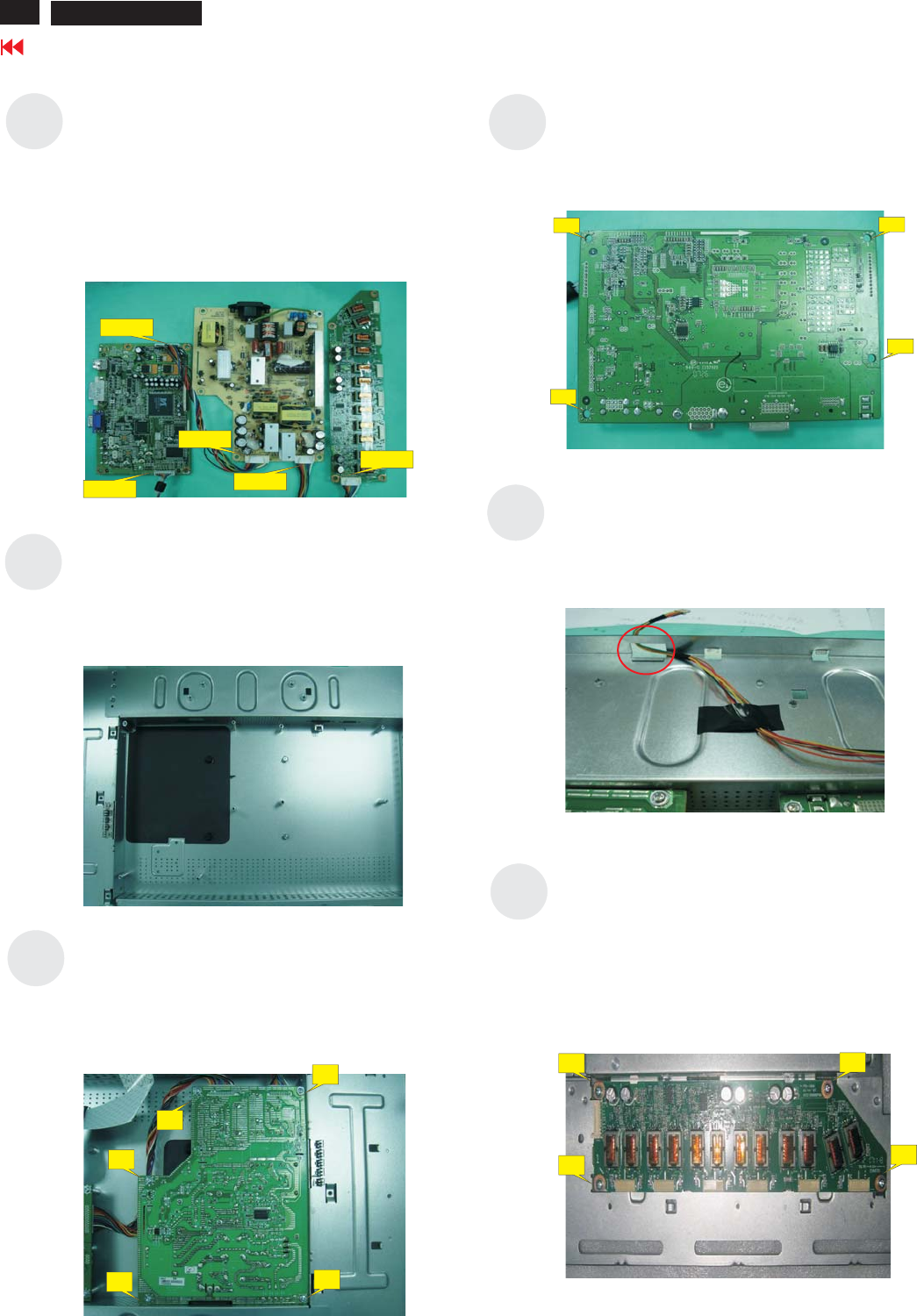
Take the key function cable out from the hole
shown as photo
Fix the function key cable with a PVC tape
Turn over the bracket chassis base then fix the
inverter board
Use a Phillips-head screwdriver screwed the
No.1~4 screws till that inverter board and bracket
chassis base firmly attached.
(No1~4 screw size=M3x6; Torque=9~10KGFxCM).
12
3
4
12
Go to cover page
ACER G24